| CPC G02B 27/0176 (2013.01) [G02B 27/0172 (2013.01); G02B 2027/0132 (2013.01); G02B 2027/0152 (2013.01); G02B 2027/0178 (2013.01)] | 13 Claims |
|
1. An electronic device, comprising:
a binocular lens provided to correspond to eyes of a wearer;
a lens frame fixed to the binocular lens and configured to be seated on a head of the wearer;
an electronic component case fixed to the lens frame;
an optical driving assembly mounted in the electronic component case and configured to emit image light to the binocular lens; and
a battery configured to supply power to the optical driving assembly,
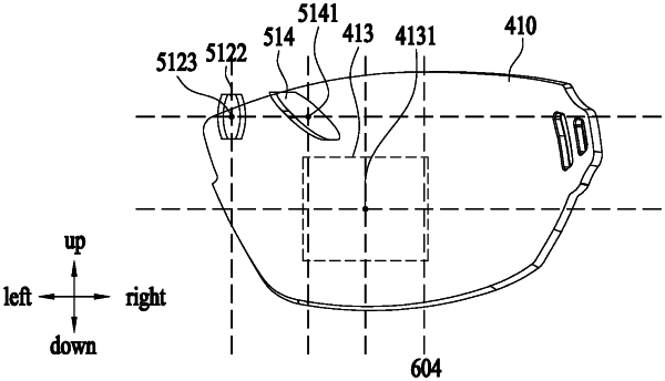
wherein a position of the electronic component case corresponds to an area between superciliary arches of the wearer,
wherein an upper transverse width of an upper portion of the electronic component case is greater than a lower transverse width of a lower portion of the electronic component case,
wherein the optical driving assembly comprises:
an image source panel configured to emit light;
an emitting lens group provided on an optical path of the light emitted from the image source panel to transmit the light emitted from the image source panel; and
a reflective mirror positioned adjacent to the emitting lens group and configured to reflect light emitted from the emitting lens group to the binocular lens directly,
wherein a height of the reflective mirror is same as a height of an exit surface of the emitting lens group, and the reflective mirror is positioned on a line extending from a stacking direction line of a plurality of lenses of the emitting lens group,
wherein the stacking direction line of the plurality of lenses of the emitting lens group corresponds to a transverse direction of the electronic device,
wherein an angle of incidence on the binocular lens from the reflective mirror is 45 degrees or less, as viewed from an upper surface of the electronic device, and
wherein the reflective mirror is provided between a reflection region of the binocular lens and the emitting lens group, in the transverse direction of the electronic device.
|