| US 11,789,268 B2 | ||
| Optical expander device | ||
| Tapani Kalervo Levola, Shenzhen (CN); Houqiang Jiang, Shenzhen (CN); Yisheng Zhu, Shenzhen (CN); and Yifan Zhu, Shenzhen (CN) | ||
| Assigned to Shenzhen Optiark Semiconductor Technologies Limited, Shenzhen (CN) | ||
| Filed by Shenzhen Optiark Semiconductor Technologies Limited, Shenzhen (CN) | ||
| Filed on Oct. 4, 2021, as Appl. No. 17/492,695. | ||
| Claims priority of application No. 202111032659.1 (CN), filed on Sep. 3, 2021. | ||
| Prior Publication US 2023/0075954 A1, Mar. 9, 2023 | ||
| Int. Cl. G02B 27/01 (2006.01); G02B 5/20 (2006.01); G02B 6/34 (2006.01); G02B 27/00 (2006.01); G02B 27/10 (2006.01); G02B 27/42 (2006.01) | ||
| CPC G02B 27/0172 (2013.01) [G02B 5/203 (2013.01); G02B 6/34 (2013.01); G02B 27/0018 (2013.01); G02B 27/1086 (2013.01); G02B 27/4272 (2013.01); G02B 2027/0112 (2013.01); G02B 2027/0123 (2013.01)] | 8 Claims |

|
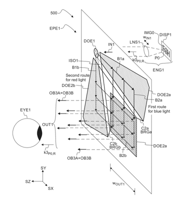
1. An optical device (EPE1) comprising a waveguide plate (SUB1), which in turn comprises:
an in-coupling element (DOE1) to form first guided light (B1a) and second guided light (B1b) by diffracting input light (IN1), a first expander element (DOE2a) to form third guided light (B2a) by diffracting the first guided light (B1a), a second expander element (DOE2b) to form fourth guided light (B2b) by diffracting the second guided light (B1b), and an out-coupling element (DOE3) to form first output light (OB3a) by diffracting the third guided light (B2a), and to form second output light (OB3b) by diffracting the fourth guided light (B2b), wherein the out-coupling element (DOE3) is arranged to form combined output light (OUT1) by combining the first output light (OB3a) with the second output light (OB3b), wherein the in-coupling element (DOE1) has a first grating period (d1a) for forming the first guided light (B1a), and wherein the in-coupling element (DOE1) has a second different grating period (d1b) for forming the second guided light (B1b), wherein the optical device (EPE1) comprises a first spectral filter region (C2a) to prevent coupling of red light from the in-coupling element (DOE1) to the out-coupling element (DOE3) via the first expander element (DOE2a), wherein the optical device (EPE1) comprises a second spectral filter region (C2b) to prevent coupling of blue light from the in-coupling element (DOE1) to the out-coupling element (DOE3) via the second expander element (DOE2b), wherein the optical device (EPE1) comprises a first Bragg grating region (BRGa), which at least partly overlaps the first spectral filter region (C2a) so as to enhance absorption of red light in the first spectral filter region (C2a), wherein the optical device (EPE1) comprises a second Bragg grating region (BRGb), which at least partly overlaps the second spectral filter region (C2b) so as to enhance absorption of blue light in the second spectral filter region (C2b); wherein the in-coupling element (DOE1) is arranged to diffract the input light (IN1) such that the first guided light (B1a) comprises light of a center point (P0) of an input image (IMG0), and such that the second guided light (B1b) comprises light of the center point (P0), wherein the out-coupling element (DOE3) is arranged to diffract the third guided light (B2a) received from the first expander element (DOE2a) such that the first output light (OB3a) comprises light of the center point (P0), wherein the out-coupling element (DOE3) is arranged to diffract the fourth guided light (B2b) received from the second expander element (DOE2b) such that the second output light (OB3b) comprises light of the center point (P0), wherein the light of the center point (P0) in the first output light (OB3a) propagates in an axial direction (k3P0,R), wherein the light of the center point (P0) in the second output light (OB3b) propagates in the same axial direction (k3P0,R). |