| CPC G02B 21/365 (2013.01) [G01N 21/6458 (2013.01); G02B 21/16 (2013.01); G02B 27/30 (2013.01); G01N 2021/6463 (2013.01)] | 15 Claims |

|
1. An optical detection device, comprising:
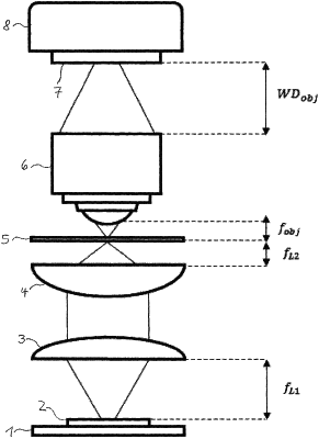
a light emission device having a light source array which comprises a multiplicity of separately electrically actuatable electric light sources which are distributed over a light emission side of the light source array in a matrix structure or in a two-dimensional geometric arrangement and are configured to emit a light pattern in a direction along a beam path that extends from the light emission side,
a light detection device having a light detection side in the beam path, facing toward, spaced a distance from, and optically coupled to the light emission side of the light source array,
an examination region in which an object to be examined is arrangeable, positioned along the beam path, between the light detection of the light detection device and the light emission side of the light source array,
an optical reduction system arranged in the beam path that extends from the light emission side of the light source array and the examination region, configured to optically demagnify the light pattern emitted by the light sources of the light source array into a demagnified light pattern in relation to the light pattern emitted by the light source array and to radiate the demagnified light pattern, in said direction, along the beam path through the examination region, and
an optical magnification system positioned, along the beam path, between the examination region and the light detection side of the light detection device, and configured to receive the demagnified light pattern radiated through the examination region, convert the received light pattern into a magnified light pattern, and project the magnified light pattern in said direction along the beam path onto the light detection side.
|