| CPC G01V 3/104 (2013.01) [H02J 50/12 (2016.02); H02J 50/60 (2016.02)] | 15 Claims |

|
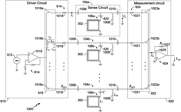
1. An apparatus for detecting objects, the apparatus comprising:
a plurality of sense circuits, each of the plurality of sense circuits comprising:
a sense coil configured to inductively sense an object and having a reactance and an equivalent series resistance at an operating frequency; and
a series capacitor electrically connected in series to the sense coil and configured to compensate for the reactance of the sense coil at an operating frequency;
a driver circuit having a plurality of outputs each electrically connected to a first terminal of a respective sense circuit of the plurality of sense circuits and configured to selectively drive a current at the operating frequency in the sense coil and the series capacitor of the respective sense circuit, the driver circuit further comprising:
a driver amplifier having a voltage source output;
a plurality of input multiplexer switches each configured to selectively connect the voltage source output to a selected one of the plurality of outputs of the driver circuit; and
a plurality of first resistors each configured to mimic a current source characteristic at each of the plurality of outputs of the driver circuit and provide a current source output to the respective sense circuit; and
a measurement circuit having a plurality of inputs each electrically connected to a second terminal of the respective sense circuit of the plurality of sense circuits and configured to selectively measure a voltage across the sense coil and the series capacitor of the respective sense circuit in response to the current in the sense coil and the series capacitor, the measurement circuit comprising:
a plurality of second resistors each configured to mimic a voltage measurement circuit characteristic at each of the plurality of inputs of the measurement circuit;
a measurement amplifier having an input with a current measurement circuit characteristic; and
a plurality of output multiplexer switches each configured to selectively connect a selected input of the plurality of inputs of the measurement circuit to the input of the measurement amplifier and provide an output of the respective sense circuit to the input of the measurement amplifier.
|