| CPC G01R 27/14 (2013.01) [H03K 17/6871 (2013.01); H03M 3/30 (2013.01)] | 15 Claims |

|
1. A circuit for measuring a resistance, comprising:
a resistive element having a resistance to be measured;
a sensor circuit to generate a differential voltage dependent on the resistance of the resistive element, the sensor circuit comprising:
a first and a second path each including a diode element and an output terminal, one of the first and second paths including the resistive element;
a reference circuit to generate a differential reference voltage, the reference circuit comprising:
a first and a second path each including a current source and a diode element the current sources configured to supply a substantially different current;
a first and a second output terminal the first output terminal configured to selectively supply a voltage from one of the first and second paths of the reference circuit and the second output terminal configured to selectively supply a voltage from the other one of the first and second paths of the reference circuit;
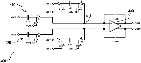
a sigma-delta converter circuit comprising a first stage and a downstream connected second stage,
the first stage comprising:
a first and a second capacitor and an integration element the first capacitor selectively coupled to one of the output terminals of the sensor circuit the second capacitor to one of the first and second output terminals of the reference circuit; and
the second stage comprising an output terminal configured to provide a bitstream dependent on the resistance to be measured.
|