| CPC G01N 1/2035 (2013.01) [G01N 30/38 (2013.01); G01N 30/7233 (2013.01); G01N 2030/027 (2013.01)] | 4 Claims |

|
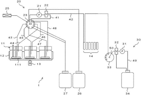
1. A sampling apparatus that samples a liquid in a container, the sampling apparatus comprising:
a circulation mechanism that circulates the liquid in the container via a circulation flow path by leading out the liquid from the container into the circulation flow path and introducing the liquid from the circulation flow path into the container; and
a flow path switching unit that is provided in the middle of the circulation flow path, and switches a flow path such that the liquid circulated in the circulation flow path flows out to a branch flow path to be sampled,
a control unit that controls a sampling amount of the liquid by controlling time for switching the flow path by the flow path switching unit,
wherein the control unit collects the liquid into the container by causing the liquid in the circulation flow path to flow back after the liquid is sampled.
|