| CPC G01J 1/0488 (2013.01) [G01J 1/0403 (2013.01); G01J 1/44 (2013.01); H01L 24/13 (2013.01); H01L 24/16 (2013.01); H01L 24/17 (2013.01); H01L 24/81 (2013.01); H01L 27/144 (2013.01); G02B 5/20 (2013.01); H01L 2224/13109 (2013.01); H01L 2224/16145 (2013.01); H01L 2224/16225 (2013.01); H01L 2224/17181 (2013.01); H01L 2224/81192 (2013.01); H01L 2924/05432 (2013.01); H01L 2924/10252 (2013.01); H01L 2924/10254 (2013.01); H01L 2924/10379 (2013.01)] | 19 Claims |

|
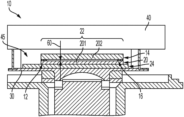
1. An optical sensor and filter assembly, comprising:
an optical sensor comprising a detector layer having first and second opposed faces and a read-out integrated circuit (ROIC) to which the first face of the detector layer is hybridized;
a filter that permits passage of one or more wavelength bands of interest of incident light toward the optical sensor; and
a mounting structure by which the filter is directly hybridized to the second face of the detector layer,
wherein the mounting structure comprises Indium strips disposed along each of the sides of the filter and Indium spheres disposed in each of the corners of the filter.
|