| CPC F23R 3/06 (2013.01) | 19 Claims |

|
1. A combustor for a turbomachine engine, the combustor comprising:
a combustion chamber;
a liner forming a boundary of the combustion chamber; and
a plurality of dilution holes through the liner to permit airflow into the combustion chamber,
wherein each dilution hole in the plurality of dilution holes has an intake aperture on a cold surface of the liner outside the combustion chamber, and an exit aperture on a hot surface of the liner inside the combustion chamber, and
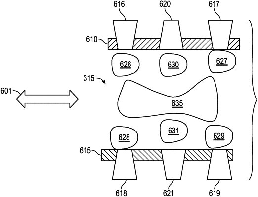
wherein the plurality of dilution holes comprises converging dilution holes and diverging dilution holes, the converging dilution holes having a converging cross-sectional profile that is wider on the cold surface of the liner and narrower on the hot surface of the liner, and the diverging dilution holes having a diverging cross-sectional profile that is wider on the hot surface of the liner and narrower on the cold surface of the liner.
|