| CPC F16D 41/088 (2013.01) [F16D 27/108 (2013.01); F16J 15/3232 (2013.01); F16D 2023/123 (2013.01)] | 17 Claims |

|
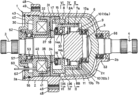
1. A rotation transmission device comprising:
a tubular case including, as a seamless integral member; a cylindrical large-diameter tubular portion,
a cylindrical small-diameter tubular portion having an inner diameter smaller than an inner dimeter of the large-diameter tubular portion, and
a coupling portion coupling the large-dimeter tubular portion and the small-diameter tubular portion to each other;
wherein one of two opposite ends of the large-diameter tubular portion remote from the small-diameter tubular portion is an open end, and one of two opposite ends of the small-diameter tubular portion remote from the large-diameter tubular portion is an open end,
an input shaft having one end thereof received in the case, and the other end thereof protruding beyond the open end of the large-diameter tubular portion of the case;
an output shaft aligned with the input shaft in a straight line, with one end of the output shaft received in the case, and the other end of the output shaft protruding beyond the open end of the small-diameter tubular portion of the case;
an inner ring disposed on a portion of the input shaft received in the case so as to rotate in unison with the input shaft;
an annular outer ring connected to a portion of the output shaft received in the case so as to rotate in unison with the output shaft, such that the annular outer ring surrounds the inner ring;
engagement elements disposed between an inner periphery of the outer ring and an outer periphery of the inner ring;
an engagement element cage supported for movement between an engaged position where the engagement elements are engaged with the outer ring and the inner ring and a disengaged position where the engagement elements are disengaged therefrom;
an annular electromagnet mounted between an inner periphery of the large-diameter tubular portion and an outer periphery of the input shaft;
an armature supported to axially move when the electromagnet is energized;
a motion converting mechanism configured to convert axial movement of the armature into a motion of the engagement element cage from one position of the engaged position and the disengaged position to the other position;
an input shaft bearing rotatably supporting the input shaft;
an output shaft bearing rotatably supporting the input shaft;
an output shaft seal member providing a seal between an outer periphery of the output shaft and an inner periphery of the open end of the small-diameter tubular portion;
an annular cover member made of aluminum, and fitted to an inner periphery of the open end of the large-diameter tubular portion so as to be axially opposed to the electromagnet;
an outer seal member providing a seal between an outer periphery of the cover member and the inner periphery of the large-diameter tubular portion; and
an inner seal member providing a seal between an inner periphery of the cover member and the outer periphery of the input shaft.
|