| CPC F15B 13/02 (2013.01) [F15B 7/001 (2013.01); F15B 21/00 (2013.01)] | 10 Claims |

|
1. A hydraulic control block for controlling a pressure medium supply of a hydraulic cylinder of a hydraulic spindle, comprising:
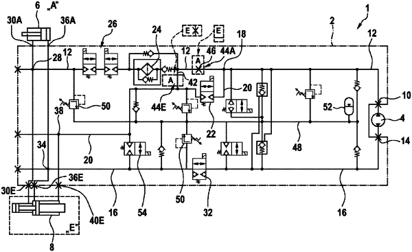
a generic hydraulic switching structure electively configurable in each of a plurality of specific hydraulic switching structures, each of the plurality of specific hydraulic switching structures having a respective hydraulic cylinder with a number of piston areas which differs from a number of piston areas in the respective hydraulic cylinders of each of the other of the plurality of specific hydraulic switching structures;
a first supply interface configured to be electively fluidically connected to at least one of a high-pressure side of a hydraulic machine of the hydraulic spindle and a low-pressure side of the hydraulic machine;
a second supply interface configured to be electively fluidically connected to at least one of the high-pressure side and the low-pressure side of the hydraulic machine;
a first working flow path configured to be electively fluidically connected to the first supply interface;
a second working flow path configured to be electively fluidically connected to the second supply interface;
a third working flow path configured to be electively fluidically connected to the first supply interface in parallel with the first working flow path;
at least one first working port branched off from the first working flow path;
at least one second working port branched off from the second working flow path;
at least one third working port branched off from the third working flow path; and
a valve in the third working flow path configured to electively close and open said third working flow path.
|