| CPC F04D 29/281 (2013.01) [F04D 29/441 (2013.01)] | 12 Claims |

|
1. A centrifugal-to-axial mixed flow blower suitable for use with a system container having a rectangular air outlet, comprising:
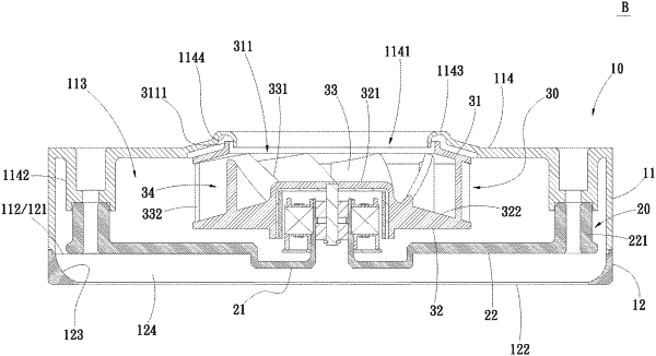
a blower enclosure including a main body and a flow guide frame; the main body having an air-in side and an opposite air-out side, which together define a blower chamber between them; the flow guide frame being located at the air-out side of the main body and configured to be adjacent to the rectangular air outlet of the system container, and including a butt joining side, an outlet side, and an air guide surface; the butt joining side and the outlet side being located at two opposite sides of the flow guide frame, and the air guide surface being formed on an inner side of the flow guide frame to extend slantly from the butt joining side to the air-out side and define a frame passage on the flow guide frame; and the frame passage being communicable with the blower chamber and the rectangular air outlet;
an impeller seat including a seat portion and two cantilever portions; the two cantilever portions being extended radially outward from an outer periphery of the seat portion and respectively having a distal end formed into a corresponding connecting section for connecting to the main body of the blower enclosure, such that the impeller seat is supported in the blower chamber and the frame passage; and
a centrifugal impeller being mounted on the seat portion of the impeller seat and located below an air inlet of the blower enclosure; the centrifugal impeller including a top impeller frame, a bottom impeller frame having a hub, and a plurality of blades located between the top and the bottom impeller frame; a radially outward declined flow passage being defined between any two adjacent blades of the plurality of blades, and the declined flow passage being respectively declined from an outer side of the hub toward an outer peripheral edge of the centrifugal impeller and communicable with the blower chamber; and air drawn in by the centrifugal impeller being guided by the declined flow passage to flow into the blower chamber in radially downward and outward directions and then pass through the frame passage, at where the air is guided by the air guide surface to the rectangular air outlet to flow into the system container.
|