| CPC F04B 39/10 (2013.01) [F04B 5/02 (2013.01); F04B 39/123 (2013.01); F04B 53/10 (2013.01); F04B 53/22 (2013.01)] | 26 Claims |

|
1. A reciprocating compressor comprising:
a compressor cylinder defining a cylinder wall;
a valve bore formed in the cylinder wall;
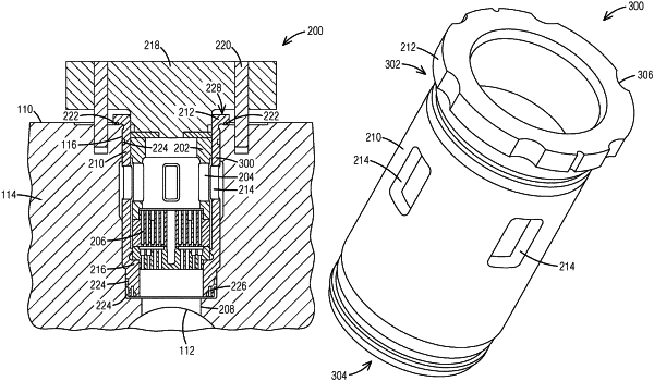
a compressor valve assembly arranged in the compressor cylinder, the compressor valve assembly comprising:
a valve liner comprising a liner body and a liner flange disposed at a first end of the liner body, the liner body disposed in the valve bore and comprising a liner window, the liner flange positioned in contact with a surface of the compressor cylinder, a valve seat coupled to an inner surface of the liner body, the valve seat comprising a seating surface formed at an end of the valve seat;
a compressor valve positioned on the seating surface of the valve seat;
a valve cage positioned on the compressor valve, the valve cage comprising a cage window;
a valve cover coupled to the valve cage to apply a bias force to retain the compressor valve on the seating surface of the valve seat; and
wherein the surface of the compressor cylinder in contact with the liner flange is perpendicular to the valve bore.
|