| CPC F03C 1/0639 (2013.01) [F03C 1/0668 (2013.01); F03C 1/0673 (2013.01); F04B 1/2078 (2013.01); F04B 1/22 (2013.01)] | 4 Claims |

|
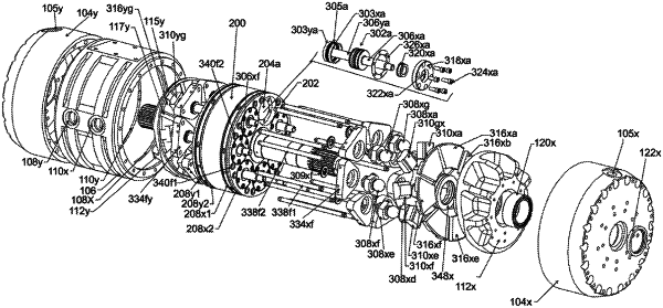
1. A hydraulic assembly comprising:
a housing having a central axis;
a rotor located along the central axis;
a first thrust plate mounted at in the housing at a first housing end around the rotor at an angle other than 90 degrees to the central axis;
a second thrust plate mounted at in the housing at a second housing end around the rotor at the same angle as the first thrust plate; and
double-acting hydraulic actuators slideably mounted between said first and said second thrust plates and fixed to the rotor;
wherein said double-acting actuators comprise:
a first set of actuators fixed to a rotatable shaft and engaging said first thrust plate,
a second set of actuators fixed to the rotatable shaft and engaging said second thrust plate,
a piston head having a first face on said first side of said double acting actuators and a second face on said second side of said double acting actuators,
a first push rod extending from said first face and a second push rod extending from said second face, the piston head mounted in a chamber that defined in a bore in the rotor and ported for hydraulic insertion and exhaust between both piston head faces and the chamber;
wherein said rotor includes a radial port for each chamber of each actuator; the hydraulic actuator further comprising:
pressure channels longitudinally spaced along said rotor and 180 degrees opposite each other and around said rotor wherein:
a first of the pressure channels is in fluid communication with the radial ports on a first side of a plurality of pistons and
a second of the pressure channels is in fluid communication with the radial ports on a second side of the plurality of pistons;
exhaust channels longitudinally spaced along a ported casing wherein:
each of the said exhaust channels is located opposite one of the pressure channels; and
the exhaust channels are in fluid communication with ports that are not in fluid communication with said pressure channel;
an I/O casing located around the rotor, the I/O casing comprising:
a first pressure orifice and a first exhaust orifice spaced longitudinally along the I/O casing;
wherein said first pressure orifice is in fluid communication with a first pressure groove in an interior face in said I/O casing that extends less than half the circumference of said I/O casing and
wherein said first exhaust orifice is in fluid communication with a first exhaust groove in an interior face in said I/O casing that extends less than half the circumference of said I/O casing;
a second pressure orifice and a second exhaust orifice spaced longitudinally along the I/O casing and opposite said first pressure orifice and said second exhaust orifice;
wherein said second pressure orifice is in fluid communication with a second pressure groove in an interior face in said I/O casing that extends less than half the circumference of said I/O casing and
wherein said second exhaust orifice is in fluid communication with a second exhaust groove in an interior face in said I/O casing that extends less than half the circumference of said I/O casing; and
wherein said pressure and exhaust channels are defined between the pressure and exhaust grooves in said I/O casing and face of said rotor;
a set of spherical ball connectors;
a set of slider components having a flat side and a concave side of the same diameter as the spherical portion of the spherical ball connectors, wherein:
said rods are each capped by one of the spherical ball connectors and one of the slider components receiving a portion of the spherical ball connectors in the concave side, and
the flat side of each slider component is in contact with a portion of one of said thrust plates.
|