| CPC F02C 6/14 (2013.01) [F02C 3/13 (2013.01); F02C 6/06 (2013.01); F02C 7/08 (2013.01); F05D 2210/12 (2013.01); F05D 2220/32 (2013.01)] | 22 Claims |

|
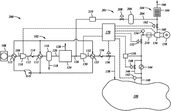
1. A power system, comprising:
a first compressor with a first inlet and a first outlet;
a nitrogen separator coupled to the first outlet, the nitrogen separator comprising a nitrogen concentrate outlet and a byproduct outlet;
a second compressor including a second inlet coupled to the nitrogen concentrate outlet, the second compressor including a second outlet for supplying concentrated nitrogen gas to a storage volume;
a turbine generator including an expander and a generator with a third inlet for coupling to the storage volume and a third outlet coupled to the second inlet such that at least a portion of the concentrated nitrogen gas exiting the third outlet flows into the second inlet; and
a vent coupled to the third outlet, wherein another portion of the concentrated nitrogen gas exiting the third outlet enters an atmosphere through the vent.
|