| CPC F01D 15/10 (2013.01) [H02K 7/1823 (2013.01); F02C 7/36 (2013.01); F02K 3/06 (2013.01); F05D 2220/36 (2013.01); F05D 2260/404 (2013.01)] | 18 Claims |

|
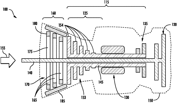
1. A hybrid propulsion system comprising:
a gas generator section comprising a high-pressure compressor;
an electrical power generator section disposed upstream of the gas generator section and configured to be driven by a power turbine;
an output power shaft mated to the power turbine and extending through a central axis of the gas generator section and the power generator section;
an engine enclosure, wherein the engine enclosure is configured to circumferentially surround the power generator section; and
a shroud disposed between the power generator section and the engine enclosure, wherein the shroud comprises non-magnetic material;
wherein the power generator section comprises:
a low pressure compressor comprising at least three axial-flow compressor stage rotating members arranged along the output power shaft, and wherein each of the at least three axial-flow compressor stage rotating members includes a magnetic portion; and
a conducting element mounted within the engine enclosure;
wherein rotation of the at least three axial-flow compressor stage rotating members relative to the conducting element generates a current transmissible by one or more coupled power output cables;
wherein the output power shaft is disposed concentrically within a turbine shaft located in the gas generator section, the output power shaft being structured to extend entirely through the gas generator section and the power generator section;
wherein the shroud is configured to reduce a clearance between the at least three rotating members and the engine enclosure, and wherein the shroud is disposed between the conducting element and the at least three axial-flow compressor stage rotating members.
|