| CPC E21B 25/02 (2013.01) [E21B 4/02 (2013.01)] | 10 Claims |

|
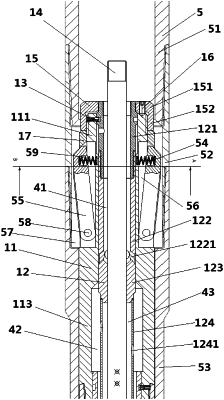
1. A drilling control mechanism of a core drilling rig, comprising a drill bit connected to a drill string and a core drill,
wherein:
the drill string is hollow and the core drill is disposed in the drill string,
an outer wall of the core drill is in sliding fit with an inner wall of the drill string,
a locking groove is disposed on the inner wall of the drill string,
a latch groove is disposed on the outer wall of the core drill,
the locking groove and the latch groove are arranged along an axial direction of the drill string,
a latch is partially disposed in the latch groove,
a pin shaft is disposed between two side walls of the latch groove,
wherein a first end of the latch is in a rotating fit with the pin shaft, an inner surface of a second end of the latch has a spring hole that is a blind hole and configured to receive a spring, and a first end of the spring is in contact with the outer wall of the core drill and a second end of the spring is in contact with a bottom surface of the spring hole,
the core drilling rig further comprises a central rod, a fluid channel activation module, an outer barrel, an outer barrel unlocking module, and a flow diverging module,
wherein the central rod extends through an inner cavity of the fluid channel activation module, the outer barrel unlocking module, and the flow diverging module, the fluid channel activation module is disposed behind the outer barrel unlocking module and the outer barrel, and the fluid channel activation module is connected to the outer barrel unlocking module.
|