| CPC E06B 9/62 (2013.01) [E06B 9/42 (2013.01); E06B 9/44 (2013.01); H02K 11/0094 (2013.01); H02K 11/33 (2016.01); E06B 9/72 (2013.01); E06B 2009/6809 (2013.01); H02J 7/0063 (2013.01); H02J 2207/20 (2020.01)] | 59 Claims |

|
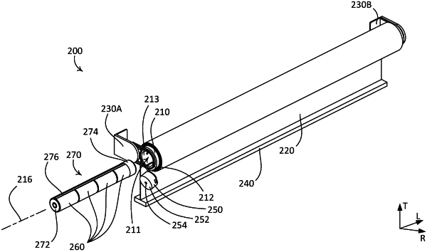
1. A motorized window treatment comprising:
a roller tube having a longitudinal axis and a cavity, the roller tube operable between an operating position and an extended position;
a flexible material that is attached to the roller tube, the flexible material operable between a raised position and a lowered position via rotation of the roller tube;
a motor drive unit disposed within the cavity of the roller tube, the motor drive unit having a motor drive unit housing, the motor drive unit comprising:
a motor configured to rotate the roller tube to operate the flexible material between the raised position and the lowered position;
a motor drive unit control circuit configured to control operation of the motor;
a battery compartment that is configured to hold a plurality of batteries for powering the motor drive unit; and
a cap that is configured to be removably secured to an end of the roller tube, the cap comprising an antenna electrically coupled to a wireless communication circuit located on a first printed circuit board housed in the cap, the wireless communication circuit configured to receive wireless signals from one or more control devices external to the motorized window treatment via the antenna, the wireless communication circuit coupled in communication with the motor drive unit control circuit for controlling the operation of the motor based on the received wireless signals;
a first mounting bracket configured to rotatably support the end of the roller tube, wherein the first mounting bracket is configured to be attached to a structure surrounding a window, and wherein the first mounting bracket defines a stationary portion and comprises a translating portion configured to translate the roller tube between the operating position and the extended position, and wherein the translating portion comprises an attachment aperture and an attachment member configured to receive a portion of the motor drive unit housing, and wherein the portion of the motor drive unit housing is accessible via the attachment aperture when the roller tube is in the extended position, and wherein the battery compartment is configured to be removed from the motor drive unit via the attachment aperture,
wherein the operating position comprises the motor drive unit housing aligned with the stationary portion of the first mounting bracket and a second mounting bracket, and wherein the extended position comprises the portion of the motor drive unit housing being accessible via the attachment aperture while still attached to the first mounting bracket and a portion of an idler assembly of the motorized window treatment received within the second mounting bracket.
|