| CPC B64D 37/08 (2013.01) [B64C 3/182 (2013.01); B64C 3/185 (2013.01); B64C 3/187 (2013.01); B64C 3/34 (2013.01)] | 20 Claims |
|
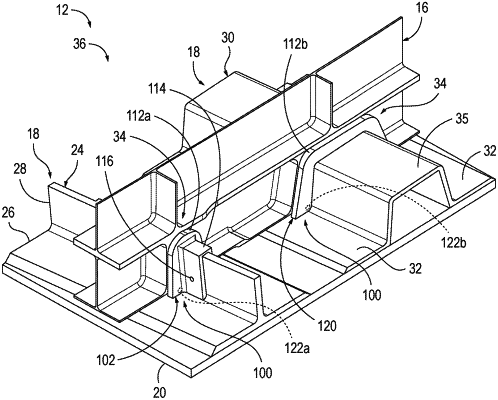
1. A method of assembling an aircraft wing, the method comprising:
adhering fuel dams to stringers; and
adhering the fuel dams to ribs, wherein the adhering the fuel dams to the ribs comprises adhering the fuel dams to respective surfaces of the ribs that define respective mouseholes of the ribs;
wherein each fuel dam comprises a fuel-dam body that defines a channel having a longitudinal axis and shaped to receive a portion of a respective stringer, wherein the fuel-dam body comprises:
a stringer adherent surface that defines the channel and is shaped to be adhered to the portion of the respective stringer;
a rib adherent surface opposite the stringer adherent surface and shaped to be adhered to a respective rib within a respective mousehole of the respective rib; and
a pair of spaced-apart flanges extending from the rib adherent surface and generally perpendicular to the longitudinal axis of the channel and positioned to project from the rib adherent surface on opposing sides of the respective rib when the rib adherent surface is adhered to the respective rib within the respective mousehole of the respective rib, wherein the spaced-apart flanges are spaced apart along the longitudinal axis of the channel.
|