| CPC B60P 7/083 (2013.01) [F16G 11/143 (2013.01)] | 18 Claims |
|
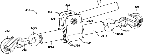
1. A load binder for securing a load to a surface by drawing respective portions of an elongated binding member closer together around the load when the load is proximate the surface so as to secure the load to the surface, the load binder comprising:
a primary link chain drive sheave coupled with a drive shaft, the drive shaft having a drive shaft axis;
an external drive coupling securely engaged with the drive shaft and the primary link chain drive sheave;
a driven link chain sheave;
an elongated threaded contraction expansion assembly including an elongated threaded member having an elongated threaded member axis; wherein the driven link chain sheave is secured to the elongated threaded member so that the elongated threaded member rotates with the driven link chain sheave when the driven link chain sheave rotates; wherein the driven link chain sheave can rotate around the elongated threaded member axis in either of two opposing first and second directions; and
a link chain moveably engaged with the driven link chain sheave and the primary link chain drive sheave such that the driven link chain sheave rotates in either the first direction or the second direction when the primary link chain drive sheave rotates around the drive shaft axis;
wherein the drive shaft axis is oriented in a generally perpendicular orientation to the elongated threaded member axis when the link chain is engaged with the primary link chain drive sheave and the driven link chain sheave; and
wherein the elongated threaded contraction expansion assembly includes first and second engaging ends positioned at opposite ends of the elongated threaded contraction expansion assembly, wherein the first and second engaging ends can be engaged with separate portions of the elongated binding member; and wherein the elongated threaded contraction expansion assembly is constructed and arranged to provide either common contraction or common extension of the first and second engaging ends when the elongated threaded member is rotated in either the first direction or the second direction, such that when each of the respective engaging ends are engaged with the separate portions of the elongated binding member, the separate portions of the elongated binding member can be drawn closer together so as to tighten the elongated binding member around the load when the elongated threaded member is rotated in the first direction, or moved farther apart so as to loosen the elongated binding member around the load when the elongated threaded member is rotated in the second direction.
|