| CPC B41J 2/06 (2013.01) [B41J 2/01 (2013.01); B41J 2/1433 (2013.01); B41J 11/0024 (2021.01); B41J 11/00216 (2021.01); B41J 2002/14491 (2013.01)] | 6 Claims |

|
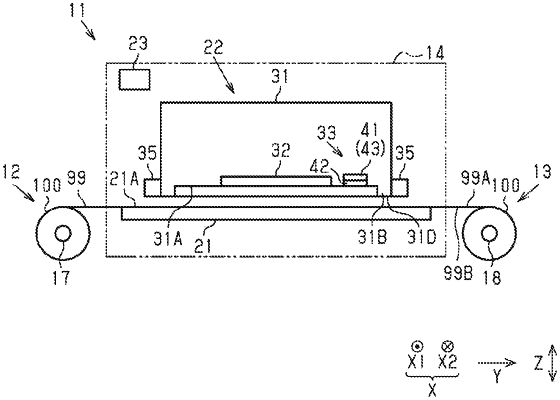
1. A liquid ejecting device comprising:
a liquid ejecting head configured to eject a liquid onto a medium;
an alternating current electric field generation unit configured to generate an alternating current electric field;
a control unit configured to control the alternating current electric field generation unit; and
a detection unit configured to detect a change in the alternating current electric field generated from the alternating current electric field generation unit, wherein
the alternating current electric field generation unit includes
a first electrode and a second electrode disposed adjacent to each other,
a high-frequency voltage generation unit configured to generate a high-frequency voltage to the first electrode and the second electrode, and
a conductor configured to electrically couple the first electrode and the second electrode to the high-frequency voltage generation unit,
the control unit is configured to stop generation of the high-frequency voltage from the high-frequency voltage generation unit to the first electrode and the second electrode based on a result detected by the detection unit, and
the second electrode surrounds the first electrode in plan view.
|
|
6. A liquid ejecting device comprising:
a liquid ejecting head configured to eject a liquid onto a medium;
an alternating current electric field generation unit configured to generate an alternating current electric field;
a control unit configured to control the alternating current electric field generation unit; and
a temperature detection unit configured to detect a temperature, wherein
the alternating current electric field generation unit includes
a first electrode and a second electrode disposed adjacent to each other,
a high-frequency voltage generation unit configured to generate a high-frequency voltage to the first electrode and the second electrode, and
a conductor configured to electrically couple the first electrode and the second electrode to the high-frequency voltage generation unit,
the temperature detection unit is configured to detect a temperature of any one of the conductor, the first electrode, and the second electrode,
the control unit is configured to stop generation of the high-frequency voltage from the high-frequency voltage generation unit to the first electrode and the second electrode based on a result detected by the temperature detection unit, and
the second electrode surrounds the first electrode in plan view.
|