| CPC B25J 9/1605 (2013.01) | 2 Claims |
|
1. A display method for displaying, on a display section, a simulation of a robot that executes work on an object with an end effector provided in an arm via a holding jig, the display method comprising:
receiving first information indicating a type of the robot, wherein the first information indicates at least lengths of arms of the robot, a number of joints of the robot, and rigidity of reduction gears of the joints;
receiving second information indicating characteristics of the end effector, wherein the second information indicates at least a length of the end effector, an attachment angle of the end effector with respect to a setting surface on which the robot is placed, a position of a working point of a working tool attached to the end effector, and a distance between the working point and the holding jig;
receiving third information indicating a position or a posture of a control point for controlling the arm;
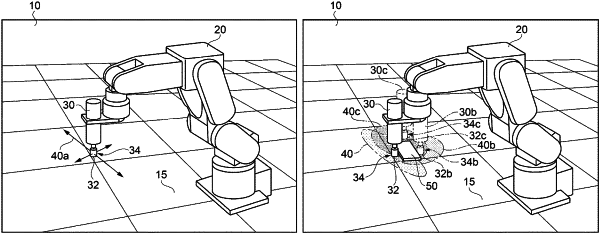
calculating rigidity at the working point of the working tool based on the first information, the second information, and the third information, wherein calculating the rigidity includes applying a force to the working point from a plurality of directions and calculating respective displacements of the working point caused by applying the force from the plurality of directions; and
displaying a result of the calculation of the rigidity on the display section as a figure that indicates the respective displacements, wherein displaying the result includes displaying the robot on the setting surface and displaying the figure over the working point of the displayed robot and the displayed setting surface, and wherein the figure indicates both direction and magnitude of the displacements caused by applying the force,
wherein the working point of the working tool is a center axis of the working tool or a side surface of the working tool that is in contact with the object.
|