| CPC A62C 35/20 (2013.01) [A62C 37/50 (2013.01); G08B 21/18 (2013.01); G08C 17/02 (2013.01)] | 19 Claims |

|
1. A hydrant comprising:
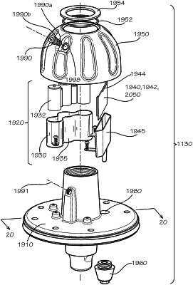
a hydrant body defining an interior cavity and comprising a bonnet secured to a top end of a barrel of the hydrant body through a flange of the bonnet, the flange defining a plug bore, the plug bore extending from an upper surface of the flange to a lower surface of the flange, the bonnet defining a bonnet cavity and a plug inserted into the plug bore, the plug formed from a non-metallic material;
a valve in sealable communication with a lower end of the barrel, the valve configured to seal the interior cavity of the hydrant from a cavity in fluid communication with an opposite side of the valve when the valve is closed;
a stem positioned at least partly inside the interior cavity of the hydrant and extending from the bonnet to the valve, the stem secured to the valve, the stem configured to open and close the valve upon operation of the valve;
a sensing device located within the interior cavity of the hydrant body and configured to measure a property of a fluid of a fluid distribution system accessed by the hydrant; and
a communications hub comprising:
a PCB positioned inside the bonnet cavity and configured to process data from the sensing device, the data corresponding to the property of the fluid of the fluid distribution system;
at least one battery in electrical communication with the PCB; and
an antenna positioned inside the bonnet cavity, the antenna in electrical communication with the PCB and configured to receive a wireless signal from the sensing device through the plug bore defined in the flange of the bonnet.
|