| CPC A61M 11/005 (2013.01) [A61M 15/001 (2014.02); A61M 15/06 (2013.01); A24F 40/10 (2020.01); A61M 2205/8206 (2013.01); B05B 17/0653 (2013.01)] | 10 Claims |

|
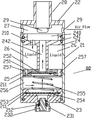
1. A high-frequency ultrasonic atomizer structure, comprising:
a main machine; and
a master frequency ultrasonic atomizer connected to the main machine, the master frequency ultrasonic atomizer comprising:
an outer sleeve, having a upper end and a lower end,
an upper cover,
a base, comprising:
a first connecting tube, extending outwards and provided with external threads, and
a first electrode, arranged in the first connecting tube,
wherein the upper cover and the base are detachably connected at the upper end and the lower end of the outer sleeve, respectively;
an inner tube support body,
an ultrasonic atomization unit,
wherein the inner tube support body and the ultrasonic atomization unit are successively arranged inside the outer sleeve;
a liquid storage chamber, formed between the inner tube support body and an inner wall of the outer sleeve;
an air flow chamber, formed between the interior of the upper cover and the inner tube support body;
a suction tube, arranged on the upper cover and in communication with the interior of the air flow chamber;
a plurality of air inlet holes, arranged in a side face of the upper cover and in communication with the interior of the air flow chamber;
wherein, the inner tube support body comprises:
a disc, arranged in the outer sleeve, connected to the upper cover and the outer sleeve, respectively, and provided with an inner chamber in communication with the air flow chamber and an oil injection hole in communication with the liquid storage chamber, and
a vent tube, having an orifice, arranged in a center of the disc and in communication with the ultrasonic atomization unit and the inner chamber of the disc;
wherein, the liquid storage chamber is an annular space defined by the disc, an outer side of the vent tube and an inner side of the outer sleeve together;
wherein, the ultrasonic atomization unit comprises:
a first fixed seat arranged at an end of the vent tube and connected to the vent tube,
a metal substrate arranged in the first fixed seat, and provided with a micropore area corresponding to the orifice of the vent tube in position,
a second fixed seat arranged on the base and spaced apart from the first fixed seat by a certain distance,
a piezoelectric ceramic piece arranged on the second fixed seat and connected to the first electrode,
a spring, arranged between the metal substrate and the piezoelectric ceramic piece, and in contact with the metal substrate and the piezoelectric ceramic piece, respectively, and
an atomization liquid chamber formed among the first fixed seat, the second fixed seat and the inner side of the outer sleeve;
wherein, the first fixed seat is provided with liquid guide holes for guiding liquid in the liquid storage chamber into the atomization liquid chamber, and the spring is immersed by the liquid in the atomization liquid chamber.
|