| CPC A47H 1/104 (2013.01) [A47H 1/06 (2013.01)] | 3 Claims |

|
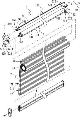
1. A zebra curtain, comprising a curtain rolling device, an upper rail disposed behind the curtain rolling device, two fixing brackets respectively arranged on a left side and a right side of a top of a window for axially connecting the upper rail and the curtain rolling device, a lower rail and a curtain sheet, wherein a starting end of the curtain sheet is fixed on the upper rail and a terminal end of the curtain sheet is fixed on the curtain rolling device to make the curtain sheet be wound around outer surfaces of the curtain rolling device, the lower rail and the upper rail, wherein the zebra curtain is characterized in that: the upper rail is provided for inserting the starting end of the curtain sheet to make the curtain sheet be wound around the outer surface of the upper rail, and the upper rail comprises:
a first shaft sleeve, located at a first end of the upper rail, the first shaft sleeve comprising a first inlay inserted into the first end of the upper rail, a first covering wall connected to one end of the first inlay and covering the first end of the upper rail, and a first protruding shaft protrudingly formed at the first covering wall and extending in an opposite direction from the first inlay, wherein the first protruding shaft is a square shaft; and
a second shaft sleeve located at a second end of the upper rail, the second shaft sleeve comprising a bearing, a second protruding shaft, a spring and a positioning piece, wherein
the bearing comprises a second inlay inserted into the second end of the upper rail, a second covering wall connected to a first end of the second inlay and covering the second end of the upper rail, a through hole formed at a second end of the second inlay, a chamber located inside the second inlay and communicating with the through hole, and an inlet formed at the second covering wall and communicating with the chamber and the through hole;
the second protruding shaft comprises a shaft rod and a square shaft connecting with the shaft rod, wherein the shaft rod penetrates into the through hole from the inlet of the second covering wall, and the second protruding shaft is configured to move back and forth inside the bearing via an action of the spring;
the spring is sleeved on an outer surface of the shaft rod and configured to be compressed or expand inside the chamber of the second inlay; and
the positioning piece is engaged with a first end of the shaft rod;
each of the two fixing brackets comprises a fixing body and a stand frame connected below the fixing body, the two stand frames on the left side and the right side are provided for connecting the first protruding shaft of the first shaft sleeve and the square shaft of the second protruding shaft, respectively;
the lower rail is arranged below the upper rail at an interval; and
the curtain sheet comprises a plurality of light-transmitting parts with a plurality of holes and a plurality of light-impermeable portions without the plurality of holes; and the plurality of light-transmitting parts and the plurality of light-impermeable portions are arranged at intervals to form a forward overlap double-layered curtain cloth,
wherein the upper rail is configured to be disconnected from the fixing bracket at the left side by pressing the second protruding shaft to compress the spring mounted inside the bearing to disassemble the upper rail, to wind the curtain sheet to adjust a position of the plurality of light-transmitting parts and the plurality of light-impermeable parts, to axially connect the first protruding shaft with the fixing bracket at the right side, and to connect the second protruding shaft with the fixing bracket at the left side by pressing the second protruding shaft and the action of the spring to assemble the upper rail, the upper rail is rotationally fixed when connected to the two fixing brackets.
|