| CPC H03L 7/081 (2013.01) | 17 Claims |

|
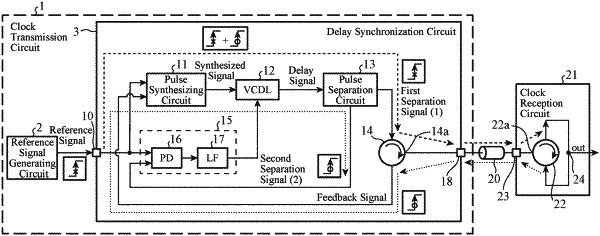
1. A delay synchronization circuit comprising:
a pulse synthesizing circuit to generate a synthesized signal including a first pulse signal synchronized with a reference signal and a second pulse signal synchronized a feedback signal;
a signal delay circuit to delay a synthesized signal generated by the pulse synthesizing circuit and output a delay signal that is a delayed synthesized signal;
a pulse separation circuit to generate a first separation signal synchronized with a first pulse signal included in a delay signal output from the signal delay circuit and generate a second separation signal synchronized with a second pulse signal included in the delay signal;
a circulator to output a first separation signal generated by the pulse separation circuit to a clock reception circuit and then output the first separation signal returned from the clock reception circuit to the pulse synthesizing circuit as the feedback signal; and
a delay-amount control circuit to control a delay amount of a synthesized signal in the signal delay circuit in accordance with a phase difference between the reference signal and the second separation signal generated by the pulse separation circuit.
|