| CPC H02P 27/08 (2013.01) [H02M 1/0009 (2021.05); H02M 7/53871 (2013.01)] | 5 Claims |

|
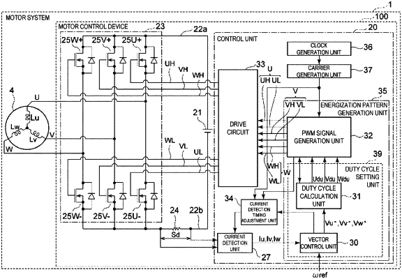
1. A motor control device, comprising:
a control unit configured to generate a PWM signal corresponding to each phase of a motor including coils of a plurality of phases;
an inverter circuit configured to drive the coil of each phase, based on the PWM signal; and
a current detector connected to a direct-current line of the inverter circuit in series, wherein
the control unit includes
a current detection unit configured to detect a current of the current detector,
a duty cycle setting unit configured to set a duty cycle of the PWM signal of each phase, based on a detection result of the current detection unit, and
a PWM signal generation unit configured to generate the PWM signal of each phase, based on the duty cycle set by the duty cycle setting unit,
one cycle of the PWM signal of each phase includes a first period and a remaining second period,
the PWM signal of each phase has a signal level changing at a timing according to the set duty cycle in the first period, and has a signal level changing at a different fixed timing in the second period, and
the current detection unit detects a current of the current detector in the second period.
|