| CPC H02M 7/539 (2013.01) [H02J 3/01 (2013.01); H02M 1/12 (2013.01)] | 20 Claims |

|
1. A power conversion device comprising:
a power converter connected to an AC grid to which a load is connected; and
a control circuitry to perform output control of the power converter, wherein
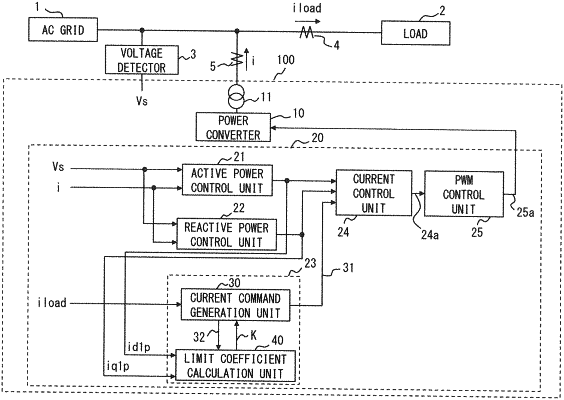
the control circuitry includes a harmonic compensation circuitry to compensate for harmonic current contained in load current by compensation current, and controls the compensation current in output current of the power converter, and
the harmonic compensation circuitry includes
a current command generation circuitry which generates a compensation current desired value for each of a plurality of frequency components, and corrects each compensation current desired value using a corresponding limit coefficient, to generate a compensation current command for each frequency component, and
a limit coefficient calculation circuitry which calculates each limit coefficient, on the basis of the compensation current desired value for each of the plurality of frequency components, and maximum voltage and maximum current that the power converter is able to output.
|