| CPC H02M 7/5387 (2013.01) [G01R 19/0084 (2013.01)] | 4 Claims |

|
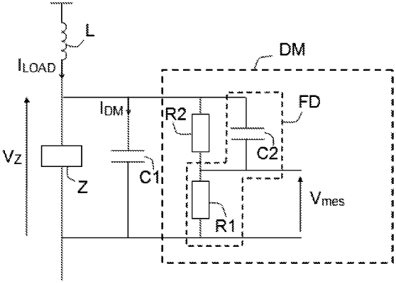
1. An inverter device (DO) intended to transform a direct voltage into a single-phase voltage, the inverter device (DO) comprising a low-pass filter, a measurement device (DM), and four power switches mounted in H-bridge configuration, said low-pass filter comprising the first capacitor (C1) and an inductor (L), said measurement device (DM) being configured to deliver a voltage corresponding to an overlay of an input voltage applied to the terminals of the measurement device (DM) and of an image voltage of a current circulating in a first capacitor (C1) to the terminals of which the input voltage is applied, the measurement device (DM) comprising:
a shunt filter (FD) intended to be mounted in parallel with the first capacitor (C1) and comprising a second capacitor (C2) and a first resistor (R1) mounted in series with the second capacitor (C2),
a second resistor (R2) mounted in parallel with the second capacitor (C2);
said H-bridge comprising two branches each comprising two switches connected in series, a first mid-point (P1) linking the two switches of a first of the two branches and a second mid-point (P2) linking the two switches of a second of the two branches, the first mid-point (P1) being linked to a first terminal of the first capacitor (C1) via the inductor (L) and the second mid-point (P2) being linked to a second terminal of the second capacitor (C2).
|