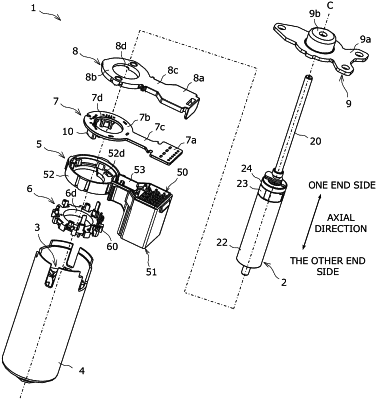
| CPC H02K 1/2726 (2013.01) [H02K 1/28 (2013.01); H02K 11/215 (2016.01)] | 5 Claims |

|
1. A rotor applied to an inner rotor brushless motor, comprising:
a rotor core including a laminate of a plurality of annular thin plate-shaped core pieces, the rotor core being configured to rotate together with a shaft in an integrated manner;
a cylindrical resin magnet mounted on an outer peripheral surface of the rotor core via a gap;
a groove-shaped adhesive admission portion in a straight line along the entire length of the rotor core in an axial direction thereof, the adhesive admission portion being recessed into the outer peripheral surface of the rotor core;
an adhesive configured to bond and fix the rotor core and the resin magnet;
a bush fixed to the rotor core and the resin magnet on one end side in the axial direction; and
a sensor magnet fixed to the bush on the one end side, the sensor magnet being configured to rotate together with the shaft in an integrated manner, wherein
the adhesive is filled in an entire adhesive allowance including both of the gap and the adhesive admission portion between the outer peripheral surface of the rotor core and an inner peripheral surface of the resin magnet, and
the bush includes a prevention surface that blocks the gap on the one end side to prevent run-off of the adhesive, and a holding portion that holds the sensor magnet.
|