| CPC H01R 13/26 (2013.01) [H01R 12/00 (2013.01); H01R 12/7005 (2013.01); H01R 12/724 (2013.01); H01R 12/75 (2013.01); H01R 13/64 (2013.01); H01R 13/6583 (2013.01); H01R 13/6585 (2013.01); H01R 13/6587 (2013.01); H01R 13/6599 (2013.01); H01R 24/28 (2013.01); H01R 43/20 (2013.01); H01R 43/26 (2013.01); H01R 13/514 (2013.01); H01R 13/6461 (2013.01); H01R 13/6473 (2013.01); H01R 24/60 (2013.01); Y10T 29/49117 (2015.01); Y10T 29/49204 (2015.01)] | 22 Claims |

|
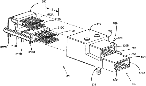
1. A receptacle adapted for mounting to a printed circuit board, the receptacle comprising:
a housing having at least one cavity, wherein each of the at least one cavity is configured to receive a mating connector inserted in an insertion direction;
a first lead assembly comprising a first housing member within the housing and a first plurality of conductive elements held in the first housing member, wherein each conductive element of the first plurality of conductive elements comprises a contact tail, a mating contact portion exposed within one cavity of the at least one cavity, and an intermediate portion coupling the contact tail to the mating contact portion, the mating contact portions of the first plurality of conductive elements being aligned in a first row extending in a row direction that is transverse to the insertion direction with contact surfaces of the mating contact portions facing in a first direction perpendicular to the row direction;
a second lead assembly comprising a second housing member within the housing and a second plurality of conductive elements held in the second housing member, wherein each conductive element of the second plurality of conductive elements comprises a contact tail, a mating contact portion exposed within one cavity of the at least one cavity, and an intermediate portion coupling the contact tail to the mating contact portion, the mating contact portions of the second plurality of conductive elements being aligned in a second row extending in the row direction with contact surfaces of the mating contact portions facing in the first direction;
a third lead assembly comprising a third housing member within the housing and a third plurality of conductive elements held in the third housing member, wherein each conductive element of the third plurality of conductive elements comprises a contact tail, a mating contact portion exposed within one cavity of the at least one cavity, and an intermediate portion coupling the contact tail to the mating contact portion, the mating contact portions of the third plurality of conductive elements being aligned in a third row extending in the row direction with contact surfaces of the mating contact portions facing in a second direction, opposite to the first direction, and perpendicular to the row direction;
a fourth lead assembly comprising a fourth housing member within the housing and a fourth plurality of conductive elements held in the fourth housing member, wherein each conductive element of the fourth plurality of conductive elements comprises a contact tail, a mating contact portion exposed within one cavity of the at least one cavity, and an intermediate portion coupling the contact tail to the mating contact portion, the mating contact portions of the fourth plurality of conductive elements being aligned in a fourth row extending in the row direction with contact surfaces of the mating contact portions facing in the second direction;
wherein:
the mating contact portions of the first plurality of conductive elements are aligned with the mating contact portions of the third plurality of conductive elements in the insertion direction,
the mating contact portions of the second plurality of conductive elements are aligned with the mating contact portions of the fourth plurality of conductive elements in the insertion direction;
the mating contact portions of the first plurality of conductive elements are offset from the mating contact portions of the second plurality of conductive elements in the insertion direction and aligned with the mating contact portions of the second plurality of conductive elements in the row direction; and
the mating contact portions of the third plurality of conductive elements are offset from the mating contact portions of the fourth plurality of conductive elements in the insertion direction and aligned with the mating contact portions of the fourth plurality of conductive elements in the row direction.
|