US 11,757,156 B2
Battery connection module
Yong Lin, ChengDu (CN); Kian-Heng Lim, Jurong Town (SG); and Shang-Xiu Zeng, ChengDu (CN)
Assigned to Molex, LLC, Lisle, IL (US)
Filed by Molex, LLC, Lisle, IL (US)
Filed on Aug. 19, 2021, as Appl. No. 17/406,374.
Claims priority of application No. 202010876773.1 (CN), filed on Aug. 27, 2020.
Prior Publication US 2022/0069424 A1, Mar. 3, 2022
Int. Cl. H01M 50/519 (2021.01); H01R 13/516 (2006.01); H01R 13/50 (2006.01); H01M 50/256 (2021.01); H01M 50/51 (2021.01); H01M 50/209 (2021.01); H05K 1/18 (2006.01)
CPC H01M 50/519 (2021.01) [H01M 50/209 (2021.01); H01M 50/256 (2021.01); H01M 50/51 (2021.01); H01R 13/50 (2013.01); H01R 13/516 (2013.01); H05K 1/189 (2013.01); H05K 2201/10189 (2013.01)] 20 Claims
OG exemplary drawing
 
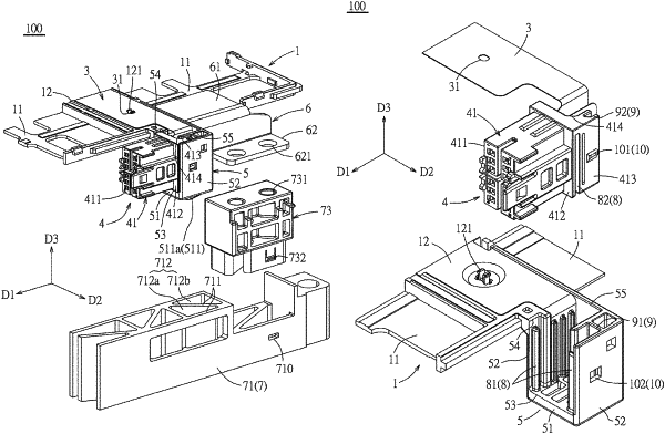
1. A battery connection module, comprising: a carrying tray; a plurality of busbars provided on the carrying tray; and a flexible circuit board provided on the carrying tray and electrically and mechanically connected to the plurality of busbars; a connector provided at an end of the flexible circuit board, the connector comprising a connector housing and a plurality of conductive terminals which are provided in the connector housing and are electrically and mechanically connected to the flexible circuit board, the connector housing having a mating portion at a front end thereof, a base at a rear end thereof and a rear supporter protruding rearwardly from a rear end surface of the base, the rear end surface of the base and the rear supporter together defining a circuit board receiving recess which is capable of partially receiving the flexible circuit board; a connector box integrally formed on one end of the carrying tray and configured to receive the connector, the connector box comprising a bottom wall and first and second side walls upstanding from opposite sides of the bottom wall, the first side wall extending between an end of the carrying tray and the bottom wall, the first and second side walls forming a front opening and an upper opening through which the connector passes to be assembled with the connector box, the mating portion extending outward from the front opening; and a first holding structure provided between the base of the connector housing and the first and second side walls of the connector box, a second holding structure provided between the rear supporter of the connector housing and the connector box, wherein during insertion of the connector housing into the connector box the first and second holding structures allow for movement of the connector housing relative to the connector box along a down direction through the upper opening while preventing movement of the connector housing relative to the connector box along a direction toward the front opening, and a third holding structure provided between the connector housing and the first and second side walls of the connector box, the third holding structure preventing movement of the connector housing relative to the connector box along an up direction when engaged.
 
10. A battery connection module, comprising: a carrying tray; a plurality of busbars on the carrying tray; and a flexible circuit board on the carrying tray and electrically and mechanically connected to the plurality of busbars; a connector provided at an end of the flexible circuit board, the connector comprising a connector housing and a plurality of conductive terminals which are provided in the connector housing and electrically and mechanically connected to the flexible circuit board; a connector box provided on one end of the carrying tray and being configured to receive the connector, the connector box comprising a bottom wall and first and second side walls, the first side wall extending between the one end of the carrying tray and the bottom wall, the first and second side walls forming a front opening and an upper opening through which the connector passes to be assembled with the connector box, the bottom wall of the connector box having a protruding portion; and a battery receiving shell configured to receive batteries therein, the battery receiving shell comprising first and second side plates having first and second end plates positioned at opposite ends thereof, wherein the first end plate is positioned below the bottom wall of the connector box, the end plate having a hollow structure and having a plurality of partitioning ribs forming a hollow groove, the protruding portion of the connector box being received within the hollow groove of the end plate, and wherein the carrying tray seats on the battery receiving shell.