| CPC H01H 50/64 (2013.01) [H01H 50/60 (2013.01)] | 13 Claims |

|
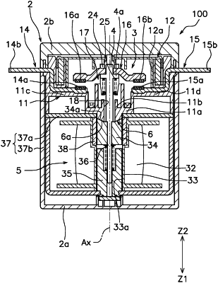
1. An electromagnetic relay, comprising:
a fixed contact;
a movable contact piece including a movable contact disposed to face the fixed contact, the movable contact piece being movable in a first direction in which the movable contact piece comes into contact with the fixed contact and in a second direction in which the movable contact piece is separated from the fixed contact;
a drive shaft connected to the movable contact piece, the drive shaft being movable in the first direction and the second direction together with the movable contact piece;
a contact case configured to house the fixed contact and the movable contact, the contact case including a contact support portion and a tubular portion, the contact support portion configured to support the fixed contact, the tubular portion located closer to the drive shaft than the contact support portion;
an electromagnetic drive device including a movable iron core that is integrally movably connected to the drive shaft, the electromagnetic drive device being configured to switch between a contact state in which the movable contact comes into contact with the fixed contact and a separate state in which the movable contact is separated from the fixed contact by moving the drive shaft with the movable iron core; and
a positioning portion configured to position the drive shaft or the movable iron core in the separate state, wherein
the drive shaft or the movable iron core includes a first inclined portion that comes into contact with the positioning portion in the separate state, the first inclined portion being inclined with respect to the first direction or the second direction,
the positioning portion comes into contact with only the first inclined portion of the drive shaft or the movable iron core in the separate state,
a gap is defined between the tubular portion and the drive shaft, and
the contact support portion and the tubular portion are disposed in the first direction relative to the movable contact.
|