| CPC F28F 9/0275 (2013.01) [F28D 7/16 (2013.01); F28D 7/1669 (2013.01); F28D 9/0018 (2013.01); B23P 15/26 (2013.01)] | 15 Claims |

|
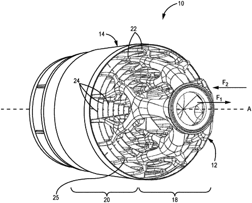
1. A heat exchanger comprising:
a first flow circuit structure having at least a first portion defined by a plurality of conduits extending from a common branched inlet to a common branched outlet, each of the plurality of conduits comprising:
an inlet section branching from the common branched inlet into a plurality of inlet section outlets;
an outlet section branching from the common branched outlet into a plurality of outlet section inlets; and
a plurality of mid-sections, each mid-section of the plurality of mid-sections fluidly connecting one of the plurality of inlet section outlets to one of the outlet section inlets, wherein mid-sections are arranged around an axis in a plurality of concentric rows; and
a second flow circuit structure comprising a plurality of walls disposed between the conduits and unconnected from the conduits such that the plurality of walls is free to move relative to the conduits and wherein the walls of the plurality of walls are joined between the conduits to form a single structure; the plurality of walls comprising:
cylinders that circumscribe each concentric row of the plurality of concentric rows of mid-sections such that radially adjacent mid-sections are separated by a cylinder; and
one or more ribs, wherein the one or more ribs extend radially and connect the cylinders such that the one or more ribs separate adjacent mid-sections within each concentric row;
wherein the cylinders extend between the common branched inlet and the common branched outlet;
wherein fluid flowing through the first flow circuit structure is fluidically isolated from fluid flowing through the second flow circuit structure.
|
|
12. A method of making a heat exchanging arrangement comprising:
forming a plurality of conduits defining at least a first portion of a first flow circuit structure, the plurality of conduits extending from a branched inlet to a branched outlet, each of the plurality of conduits comprising:
an inlet section branching from the branched inlet into a plurality of inlet section outlets;
an outlet section branching from the branched outlet into a plurality of outlet section inlets; and
a plurality of mid-sections, each of the plurality of mid-sections fluidly connecting one of the plurality of inlet section outlets to one of the outlet section inlets, wherein mid-sections are arranged around an axis in a plurality of concentric rows; and
forming a plurality of walls positioned between the conduits defining at least a second portion of a second flow circuit structure, wherein the plurality of walls is unconnected from the conduits such that the plurality of walls is free to move relative to the first portion and wherein walls of the plurality of walls are joined between the conduits to form a single structure the plurality of walls comprising:
cylinders that circumscribe each concentric row of the plurality of concentric rows of mid-sections such that radially adjacent mid-sections are separated by a cylinder; and
one or more ribs, wherein the one or more ribs extend radially and connect the cylinders such that the one or more ribs separate adjacent mid-sections within each concentric row;
wherein the cylinders extend between the common branched inlet and the common branched outlet;
wherein fluid flowing through the first flow circuit structure is fluidly isolated from fluid flowing through the second flow circuit structure.
|