| CPC F25B 13/00 (2013.01) [F25B 39/00 (2013.01); F25B 41/26 (2021.01); F25B 49/02 (2013.01); F25B 2313/0292 (2013.01); F25B 2313/02741 (2013.01); F25B 2500/222 (2013.01); F25B 2600/2515 (2013.01)] | 20 Claims |

|
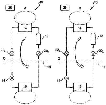
1. A refrigerant control system, comprising:
a reversing valve including:
a first inlet configured to receive refrigerant output from a condenser;
a first outlet configured to output refrigerant to an inlet of an evaporator located inside of a building;
a second inlet configured to receive refrigerant output from the evaporator; and
a second outlet configured to output refrigerant to an inlet of a compressor that pumps refrigerant to the condenser;
a reversing module configured to:
selectively actuate the reversing valve to a first position such that:
refrigerant flows directly from the second inlet to the second outlet; and
refrigerant flows directly from the first inlet to the first outlet; and
selectively actuate the reversing valve to a second position such that:
refrigerant flows directly from the second inlet to the first outlet; and
refrigerant flows directly from the first inlet to the second outlet.
|