| CPC F16D 3/12 (2013.01) [F16F 15/134 (2013.01); F16H 45/02 (2013.01); F16H 2045/0221 (2013.01)] | 7 Claims |

|
1. A torsional vibration reduction apparatus, comprising:
an input member of a rotation driving source side;
an output member of a driven body side;
input member side spring receiving portions which are plurally disposed on said input member at intervals in a circumferential direction, each including a spring pedestal opposite to said circumferential direction from each other;
output member side spring receiving portions which are plurally disposed on said output member at intervals in said circumferential direction and are paired with said respective input member side spring receiving portions opposite to an axial direction, each including a spring pedestal opposite to said circumferential direction from each other; and
coil springs which are disposed between respective pairs of said input member side spring receiving portions and said output member side spring receiving portions which are opposite to said axial direction,
wherein, with respect to a rotation displacement that rotation of said output member to that of said input member is same as rotational direction of said rotation driving source (forward rotation), elastic deformation of said coil springs between said forward rotation side spring pedestals of said output member and said forward rotation side spring pedestals of said input member is occurred;
wherein, with respect to a rotation displacement that said rotation of said output member to that of said input member is opposite to said rotational direction of said rotation driving source (reverse rotation), elastic deformation of said coil springs between said reverse rotation side spring pedestals of said output member and said reverse rotation side spring pedestals of said input member is occurred;
wherein said rotation displacement is reduced by said elastic deformation of said coil springs; and
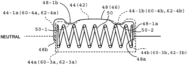
wherein respective pairs of said input member side spring receiving portions and said output member side spring receiving portions comprise a pair of guide portions to permit a local contact to said respective coil springs between circumferential direction center portions of said input member side and said output member side in an inner circumferential surface opposite to an outer circumference of said coil spring and said spring pedestals of said input member side and said output member side for slidably guiding coil spring outer circumferential portions when occurring said elastic deformation of said coil springs under centrifugal force;
wherein, in respective pairs of said input member side spring receiving portions and said output member side spring receiving portions, one of a pair of said guide portions which are disposed at said forward rotation side and said reverse rotation side in one of said input member side spring receiving portion and said output member side spring receiving portion makes protrusion heights to radial inward set to high, one of a pair of said guide portions which are disposed at said forward rotation side and said reverse rotation side in the other of said input member side spring receiving portion and said output member side spring receiving portion makes protrusion heights to radial inward set to low, the other of a pair of said guide portions in the other of said input member side spring receiving portion and said output member side spring receiving portion makes protrusion heights to radial inward set to low, the other of a pair of said guide portions in the other of said input member side spring receiving portion and said output member side spring receiving portion makes protrusion heights to radial inward set to high; and
wherein, in rotation fluctuation of one of said forward rotation and said reverse rotation, sliding guide to said centrifugal force in respective pairs of said input member side spring receiving portions and said output member side spring receiving portions is performed by said input member side spring receiving portions and said output member side spring receiving portions whose protrusion heights are high, and in rotation fluctuation of the other of said forward rotation and said reverse rotation, sliding guide to said centrifugal force in respective pairs of said input member side spring receiving portions and said output member side spring receiving portions is performed by said input member side spring receiving portions and said output member side spring receiving portions whose protrusion heights are low.
|