| CPC F02K 3/115 (2013.01) [F01D 25/12 (2013.01); F02C 7/14 (2013.01); F28F 1/022 (2013.01); F28F 1/26 (2013.01); F05D 2240/81 (2013.01); F05D 2260/213 (2013.01); F05D 2260/22141 (2013.01); F28F 2220/00 (2013.01)] | 10 Claims |

|
1. An annular heat exchanger of a longitudinal axis for a turbomachine, comprising:
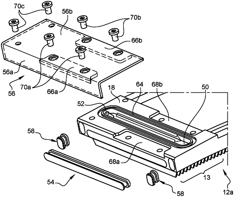
a one-piece annular part comprising a first fluid circuit comprising a first conduit and a second conduit extending annularly, wherein the first conduit and the second conduit open into a first cavity formed at a circumferential first end of said annular part, wherein a plurality of removable sealing means is attached to said first end are configured to allow a flow of fluid from the second conduit, into the first cavity and then into the first conduit, wherein a second fluidic circuit comprising a third conduit and a fourth conduit is arranged on either side of the first conduit and the second conduit of the first fluid circuit in a circumferential direction extending annularly and perpendicular to the longitudinal axis, and wherein the third conduit and the fourth conduit of the second fluidic circuit open into a second cavity formed at the first circumferential end of said annular part and arranged radially outside the first cavity in a direction perpendicular to the longitudinal axis and the circumferential direction, the plurality of removable sealing means also being attached at said first end so as to allow a flow of fluid from the fourth conduit of the second fluidic circuit, into the second cavity and then into the third conduit of the second fluidic circuit.
|