| CPC F01N 3/28 (2013.01) [F01N 3/2073 (2013.01); F01N 3/34 (2013.01)] | 18 Claims |

|
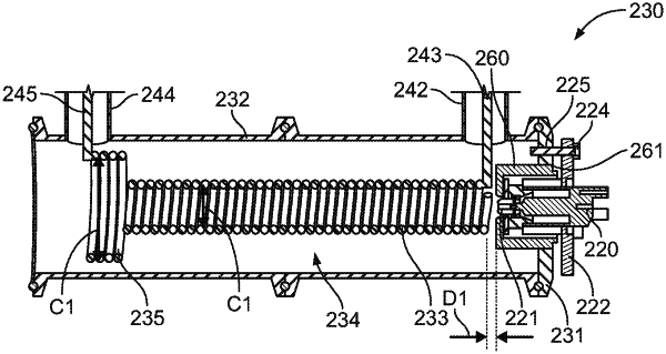
1. An ammonia generating apparatus comprising:
a housing comprising a first end wall on which a reductant injector configured to insert a reductant into the housing is mountable; and
a heating coil assembly disposed within the housing, the heating coil assembly comprising:
a first heating coil having a first heating coil first end located proximate to the reductant injector and a first heating coil second end opposite the first heating coil first end, the first heating coil having a first cross-sectional width, and
a second heating coil located proximate to the first heating coil second end of the first heating coil and axially aligned with the first heating coil, the second heating coil having a second cross-sectional width larger than the first cross-sectional width,
wherein a first end of the heating coil assembly is located proximate to a location of the first end wall where a reductant injector tip of the reductant injector is located when the reductant injector is mounted on the first end wall, and wherein the heating coil assembly is configured to generate heat sufficient to thermolyze the reductant to generate ammonia and reaction byproducts, in response to an electric current being passed therethrough.
|