| CPC F01N 3/2033 (2013.01) [F01N 3/32 (2013.01); F01N 3/36 (2013.01); F01N 3/38 (2013.01); F01N 2240/14 (2013.01); F01N 2610/03 (2013.01); F01N 2610/146 (2013.01); F01N 2900/1406 (2013.01)] | 10 Claims |

|
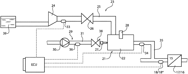
1. A method to control an exhaust gas after-treatment system (14) for an exhaust system (2) of an internal combustion engine (1) having an exhaust duct (10); the system (14) comprises at least one catalytic converter (15, 17) arranged along the exhaust duct (10) and a burner (21), which is suited to introduce exhaust gases into the exhaust duct (10) to speed up the heating of said at least one catalytic converter (15, 17), wherein inside the burner (21) there is defined a combustion chamber (22), which receives fresh air through an air feeding circuit (23), which is provided with a pumping device (24) housed along a first duct (25), and receives fuel from an injector (27) for injecting fuel into the combustion chamber (22), and a spark plug (28) coupled to the burner (21) for the ignition of the mixture present inside the combustion chamber (22); the method comprises the steps of:
housing a pressure sensor (33, 34) along the first duct (25) interposed between the pumping device (24) and the burner (21) or along a second duct (35) leaving the burner (21);
acquiring the pressure signal (P33) detected by said pressure sensor (33, 34) following the combustion inside the combustion chamber (22); and
controlling the combustion inside the combustion chamber (22), i.e. controlling an objective quantity (mFUEL-OBJ) of fuel to be injected into the combustion chamber (22) and an objective quantity (mFUEL-OBJ) of air to be fed to the combustion chamber (22), as a function of a high-frequency content (P33_HF) of the pressure signal (P33) detected by said pressure sensor (33, 34).
|