| CPC E02F 9/2004 (2013.01) [B60K 23/02 (2013.01); B62D 33/0617 (2013.01); F16D 23/12 (2013.01); B60Y 2200/221 (2013.01); B62D 33/0604 (2013.01); E02F 9/16 (2013.01); F16D 2023/126 (2013.01)] | 5 Claims |

|
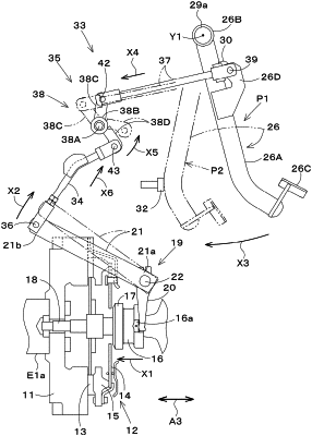
1. A working vehicle comprising:
a vehicle body;
a cabin mounted on the vehicle body with one or more anti-vibration mounts;
a pedal shaft provided in the cabin;
a clutch pedal pivotally supported by the pedal shaft;
a clutch provided on the vehicle body;
a clutch operator to engage and disengage the clutch;
a linkage including first and second ends, the first end of the linkage being connected to the clutch operator;
a linkage lock to interlock the clutch pedal with the second end of the linkage so that vibrations of the cabin are reduced or prevented from being transmitted to the clutch; and
a support frame disposed forward of the cabin and attached to the vehicle body, wherein
the clutch pedal includes:
a pedal arm extending lengthwise in a vertical direction and having an upper portion pivotally supported by the pedal shaft,
a pedaling member fixed to a lower portion of the pedal arm, and
a connecting stay disposed on a side of the upper portion of the pedal arm and fixed to the pedal arm,
the linkage lock includes:
an interlocking linkage having a rear end pivotally supported on the connecting stay at a position lower than the pedal shaft and rearward of the upper portion of the pedal arm, the interlocking linkage extending downwardly forward from the connecting stay, and
an intermediate linkage to interlock the linkage with a front end of the interlocking linkage, and
the intermediate linkage includes:
a linkage support shaft attached to the support frame,
a pivoting boss rotatably provided on the linkage support shaft,
a first linkage stay fixed to an upper portion of the pivoting boss such that the first linkage stay protrudes upward and pivotally supporting the front end of the interlocking linkage, and
a second linkage stay fixed to a lower portion of the pivoting boss such that the second linkage stay protrudes downward and pivotally supporting the second end of the linkage.
|