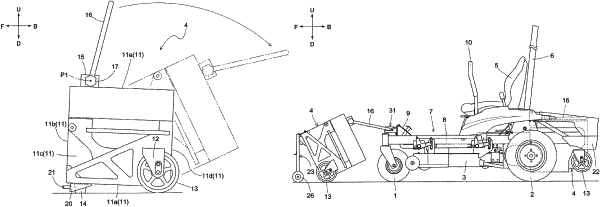
| CPC B62B 1/12 (2013.01) [B62B 5/0079 (2013.01)] | 22 Claims |

|
1. A movement assisting tool for attachment to a battery unit comprising a main body portion that accommodates a battery, a wheel provided in one portion of a lower portion of the main body portion, and a ground contact portion provided in another portion of the lower portion of the main body portion, the movement assisting tool comprising:
an attachment portion that can be attached to and removed from the main body portion;
a leg portion that is coupled to the attachment portion and extends from the attachment portion; and
a moving wheel supported by an extension portion of the leg portion,
wherein, in a state where the attachment portion is attached to the main body portion and the moving wheel is touching the ground, the battery unit is in an inclined orientation in which the wheel is touching the ground and the ground contact portion is raised above the ground,
wherein the attachment portion can be attached to and removed from the other portion of the lower portion of the main body portion,
wherein in the other portion of the lower portion of the main body portion, the attachment portion can be attached so as to span a bottom portion of the main body portion and a vertical wall portion of the main body portion that is connected to the bottom portion,
wherein the attachment portion comprises a bottom attachment portion that can be attached to and removed from the bottom portion of the main body portion, and a vertical wall attachment portion that can be attached to and removed from the vertical wall portion of the main body portion,
wherein the bottom attachment portion and the vertical wall attachment portion can be attached and removed in the same direction extending along the bottom portion of the main body portion or the same direction extending along the vertical wall portion of the main body portion, and
wherein:
one of the bottom attachment portion and the vertical wall attachment portion is an opening portion formed in the attachment portion,
another one of the bottom attachment portion and the vertical wall attachment portion is a pin or a boss portion that is coupled to the attachment portion,
one of the bottom attachment portion and the vertical wall attachment portion is attached to the main body portion by a bolt being inserted into the opening portion and screwed to the main body portion, and
the other of the bottom attachment portion and the vertical wall attachment portion is attached to the main body portion by the pin or the boss portion being inserted into a boss portion or a pin of the main body portion.
|