| CPC B41J 2/14233 (2013.01) [B41J 2/161 (2013.01); B41J 2/164 (2013.01); H10N 30/877 (2023.02); H10N 30/2047 (2023.02); H10N 30/8554 (2023.02)] | 13 Claims |

|
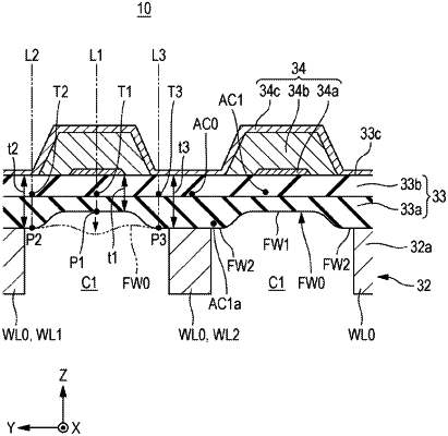
1. Liquid discharging head comprising:
a pressure chamber partitioning portion that includes a plurality of partitioning walls that partition a pressure chamber in which a pressure to discharge a liquid is applied to the liquid from another pressure chamber;
a diaphragm that includes a wall surface that faces the pressure chamber; and
a piezoelectric substance, the pressure chamber partitioning portion, the diaphragm, and the piezoelectric substance being provided in order in a first direction, wherein
the plurality of partitioning walls include a first partitioning wall and a second partitioning wall,
the pressure chamber is located between the first partitioning wall and the second partitioning wall in a second direction that intersects the first direction,
the wall surface of the diaphragm includes a first portion at a first position, in which a distance between the first position and the first partitioning wall in the second direction is equivalent to or smaller than a distance between the first position and the second partitioning wall in the second direction, and
the wall surface of the diaphragm includes a second portion at a second position between the first position and the first partitioning wall in the second direction, and
the second portion, the first portion, and a side of the diaphragm opposite from the wall surface and the pressure chamber at the second position, are disposed in this order in the first direction,
wherein, in the first direction, a portion of the side of the diaphragm opposite from the first portion is further from the pressure chamber than a portion of the side of the diaphragm opposite the second portion.
|