| CPC B41J 2/04581 (2013.01) [B41J 2/04588 (2013.01); B41J 2/1433 (2013.01); B41J 2/14201 (2013.01)] | 7 Claims |

|
1. A liquid ejection apparatus comprising:
a head unit that ejects a liquid; and
a control unit that controls an operation of the head unit,
the head unit including
a drive signal output circuit that outputs a drive signal,
a first substrate on which the drive signal output circuit is provided,
a first ejection head including a piezoelectric element driven by the drive signal, a first switching circuit that switches whether to supply the drive signal to the piezoelectric element, and a first nozzle plate including a first nozzle from which a liquid is ejected by driving the piezoelectric element,
an integrated circuit that is electrically coupled to the drive signal output circuit, and
a second substrate on which the integrated circuit is provided,
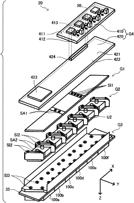
the drive signal output circuit, the first substrate, the first ejection head being arranged such that the first substrate is disposed between the drive signal output circuit and the first ejection head in an arrangement direction, and such that the drive signal output circuit and the piezoelectric element overlap each other in the arrangement direction,
the first substrate including a first face and a second face opposite to the first face in the arrangement direction,
the drive signal output circuit being provided on the first face,
a shortest distance between the first nozzle plate and the second face being shorter than a shortest distance between the first nozzle plate and the first face,
the second substrate having a third face and a fourth face,
the second substrate being electrically coupled to the first substrate, and
the integrated circuit being provided on the third face, wherein
at least part of the integrated circuit does not overlap the first substrate in a direction from the third face toward the fourth face.
|