| CPC B29C 45/13 (2013.01) [B29C 45/2703 (2013.01); B29C 45/2725 (2013.01); B29C 45/281 (2013.01); B29C 45/762 (2013.01); B29C 45/77 (2013.01); G05D 7/0113 (2013.01); G05D 7/0635 (2013.01); B29C 2045/0032 (2013.01); B29C 2045/279 (2013.01); B29C 2045/2865 (2013.01); B29C 2945/7607 (2013.01); B29C 2945/76043 (2013.01); B29C 2945/76056 (2013.01); B29C 2945/76086 (2013.01); B29C 2945/76093 (2013.01); B29C 2945/76167 (2013.01); B29C 2945/76187 (2013.01); B29C 2945/76287 (2013.01); B29C 2945/76381 (2013.01); B29C 2945/76454 (2013.01); B29C 2945/76488 (2013.01); B29C 2945/76555 (2013.01); B29C 2945/76558 (2013.01); B29C 2945/76648 (2013.01); B29C 2945/76859 (2013.01); B29C 2945/76876 (2013.01); B29C 2945/76936 (2013.01)] | 23 Claims |

|
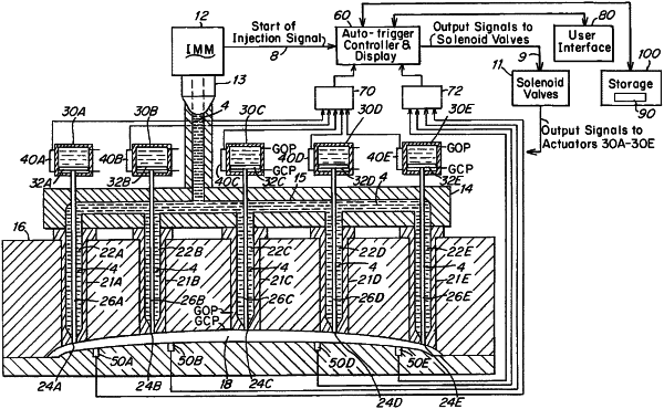
1. A method of operating an injection molding system for initiating flow of a fluid material into multiple gates of a mold cavity during an injection cycle, wherein the system includes:
a first selected valve comprising a first fluid flow passage having a first gate to the cavity, a first valve pin driven reciprocally along an axial upstream downstream path of travel through the first flow passage by a first actuator between gate open and gate closed positions,
one or more downstream valves, each downstream valve comprising a downstream fluid flow passage having a downstream gate to the cavity disposed downstream of the first gate, a downstream valve pin driven reciprocally along an axial upstream downstream path of travel through the downstream fluid flow passage by a downstream actuator between a gate open and a gate closed position the method comprising:
detecting, at a downstream detection time, a select property of a flow front of the fluid material flowing downstream at a trigger position within the cavity disposed between the first gate and at least one selected downstream gate wherein,
instructing the actuator of the valve associated with the at least one selected downstream gate, or a control valve for that actuator, to withdraw the valve pin from the gate closed position at an instruction time (X) comprising a predetermined open gate target time (X) following the downstream detection time,
detecting, at an actual open gate time, withdrawal of the valve pin from the at least one selected downstream gate,
determining an adjusted instruction time (X′), for use on a subsequent injection cycle, wherein the determining step comprises decreasing the time of instruction to the valve pin to open on a subsequent injection cycle by an adjustment time equal to any delay in time (Y) between the predetermined open gate target time (X) and the actual open gate time (A).
|