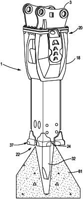
| CPC B25D 17/22 (2013.01) [E02F 3/966 (2013.01); B25D 2217/0057 (2013.01)] | 2 Claims |

|
1. A dust suppression system, comprising:
a water hose routed within a power cell of a demolition hammer; and
a connector channel internal of one or more walls of a front head of the demolition hammer and having a first branch extending internally through a first wall of the one or more walls from a proximal end of the front head at which the water hose is connected to a distal end of the front head, the water hose being configured to deliver water from outside of the demolition hammer to a connection valve on the proximal end of the front head, and the first branch of the internal connector channel being configured to deliver the water from the connection valve to a first nozzle of one or more nozzles located at the distal end of the front head wherein:
the front head comprises four walls of the one or more walls and a center aperture, the center aperture supporting a work tool of the demolition hammer,
the connector channel has a second branch that extends through a second wall of the one or more walls, the second branch configured to be curved and extends internally inside of the first wall and the second wall,
the second branch is configured to deliver the water from the first branch to a third branch of the connector channel, the third branch extending internally through a third wall of the one or more walls from the second branch to the distal end of the front head, the third branch configured to deliver the water to a second nozzle of the one or more nozzles, and the second nozzle being located at the distal end of the front head,
the second branch is circular, extending through the first wall, the second wall, the third wall, and a fourth wall of the one or more walls,
the front head includes a threaded portion, and at least one of the one or more nozzles is threaded, allowing the at least one nozzle to be screwed into the front head and wherein the at least one nozzle is conical,
in which the water hose is routed within the power cell by routing the water hose from the connection valve and through an area above the front head, defined by a first wall, a second wall, a third wall, and a fourth wall of the one or more walls, to the connection valve, and
the connector channel is configured to cool the front head between 200 and 300 degrees Celsius when the water is flowing through the connector channel.
|