| CPC A61M 15/06 (2013.01) [A24F 40/40 (2020.01); A24F 40/42 (2020.01); A61M 11/042 (2014.02); H02J 7/0034 (2013.01); H02J 7/0044 (2013.01); H05B 1/0244 (2013.01); A24F 40/10 (2020.01); A61M 15/002 (2014.02); A61M 15/0015 (2014.02); A61M 15/0016 (2014.02); A61M 2016/0021 (2013.01); A61M 2205/3331 (2013.01); A61M 2205/3368 (2013.01); A61M 2205/3606 (2013.01); A61M 2205/3653 (2013.01); A61M 2205/8206 (2013.01); A61M 2205/8237 (2013.01); H02J 7/00 (2013.01)] | 21 Claims |

|
1. A device for generating an inhalable aerosol comprising:
a cartridge having a proximal end and a distal end opposite the proximal end, the cartridge comprising a first electrical contact and a second electrical contact disposed proximate the distal end of the cartridge, the first electrical contact and the second electrical contact electrically isolated and disposed in a plane substantially parallel to the distal end of the cartridge;
a body including a receptacle configured to insertably receive the cartridge through a proximal end of the body, the receptacle terminating in a proximal edge, a distal end of the body opposite the proximal end of the body along a longitudinal dimension of the body;
a storage compartment configured to hold a vaporizable material;
a heater disposed proximate to the distal end of the cartridge, the heater configured to heat the vaporizable material to generate a vapor;
a separable mouthpiece disposed proximate to the proximal end of the cartridge and attached to the storage compartment, the separable mouthpiece comprising a condensation chamber, the condensation chamber in fluid communication with the heater, the separable mouthpiece further comprising an aerosol outlet in fluid communication with the condensation chamber;
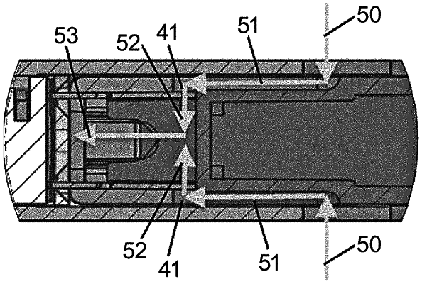
a first airflow path configured to deliver air towards the heater, the first airflow path comprising a first inlet near the proximal edge of the receptacle, a portion of the first airflow path situated between the distal end of the cartridge and the first inlet along the longitudinal dimension of the body when the cartridge is insertably received in the receptacle; and
a second airflow path configured to deliver air towards the heater, the second airflow path comprising a second inlet near the proximal edge of the receptacle, a portion of the second airflow path situated between the distal end of the cartridge and the second inlet along the longitudinal dimension of the body when the cartridge is insertably received in the receptacle, wherein the cartridge and the receptacle are configured to form the first airflow path and the second airflow path between a plurality of exterior surfaces of the cartridge and a plurality of internal surfaces of the receptacle when the cartridge is insertably received in the receptacle.
|