| CPC A61H 9/0071 (2013.01) [B60N 2/976 (2018.02); A61H 9/0078 (2013.01); A61H 2201/0149 (2013.01); A61H 2201/0169 (2013.01); A61H 2201/1207 (2013.01); A61H 2201/1238 (2013.01); A61H 2201/1409 (2013.01); A61H 2201/5056 (2013.01); B60N 2/914 (2018.02)] | 20 Claims |

|
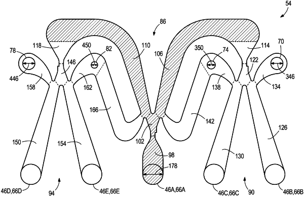
1. A pneumatic module having an air passage formed therein, the air passage comprising:
an air inlet configured to receive a source of pressurized air;
a first subsystem including an air splitter in fluid communication with the air inlet, the air splitter in fluid communication with a second subsystem and a third subsystem, wherein the air splitter is configured to create two unequal air pressure fields to deflect an airflow from the air inlet to the second subsystem,
wherein the second subsystem includes
a first air bladder and a second air bladder each in fluid communication with the air splitter, and
a first feedback passage in fluid communication with the second air bladder and the first subsystem,
wherein the second subsystem is configured to create two unequal air pressure fields to deflect the airflow toward the first air bladder to inflate the first air bladder, wherein the second subsystem is configured such that when the first air bladder reaches a first threshold air pressure, a first backpressure from the first air bladder causes the second subsystem to switch and deflect the air flow to the second air bladder such that the second air bladder inflates and the first air bladder deflates, and
wherein the second subsystem is configured such that when the second air bladder reaches a second threshold air pressure, a second backpressure from the second air bladder is generated in the first feedback passage, wherein the second backpressure causes the air splitter to switch and deflect the airflow from the second subsystem to the third subsystem, and
wherein the third subsystem includes
a third air bladder and a fourth air bladder each in fluid communication with the air splitter, and
a second feedback passage in fluid communication with the fourth air bladder and the first subsystem,
wherein the third subsystem is configured to create two unequal air pressure fields to deflect the airflow toward the third air bladder to inflate the third air bladder, wherein the third subsystem is configured such that when the third air bladder reaches a third threshold air pressure, a third backpressure from the third air bladder causes the third subsystem to switch and deflect the air flow to the fourth air bladder such that the fourth air bladder inflates and the third air bladder deflates, and
wherein the third subsystem is configured such that when the fourth air bladder reaches a fourth threshold air pressure, a fourth backpressure from the fourth air bladder is generated in the second feedback passage, wherein the fourth backpressure causes the air splitter to switch and deflect to the airflow from the third subsystem to the second subsystem.
|