| CPC A61F 2/4425 (2013.01) [A61F 2/447 (2013.01); A61F 2/30771 (2013.01); A61F 2/4611 (2013.01); A61F 2002/30471 (2013.01); A61F 2002/30556 (2013.01); A61F 2002/30579 (2013.01); A61F 2002/4629 (2013.01); A61F 2220/0025 (2013.01); A61F 2310/00023 (2013.01)] | 17 Claims |
|
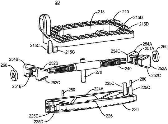
1. An expandable spinal implant, the expandable spinal implant comprising:
a first endplate, the first endplate including:
a first outer surface and a first inner surface opposite the first outer surface, the first inner surface including a first plurality of ramps and at least one first channel;
a first endplate first end and a first endplate second end opposite the first endplate first end, a first endplate first lateral surface and a first endplate second lateral surface opposite the first endplate first lateral surface;
a second endplate, the second endplate including:
a second outer surface and a second inner surface opposite the second outer surface, the second inner surface including a second plurality of ramps and at least one second channel;
a second endplate first end and a second endplate second end opposite the second endplate first end, a second endplate first lateral surface and a second endplate second lateral surface opposite the second endplate first lateral surface,
an expansion mechanism disposed between the first endplate and the second endplate, the expansion mechanism including:
a first wedge disposed between the first endplate and second endplate, the first wedge including:
a first wedge first end including a first upper surface and a first lower surface, a first wedge second end including a second upper surface and a second lower surface, wherein the first wedge comprises a first wedge aperture between the first wedge first end and the first wedge second end; and
at least one first protrusion, each first protrusion being mated with a corresponding first channel of the at least one first channel;
a second wedge disposed between the first endplate and second endplate, the second wedge including:
a second wedge first end including a third upper surface and a third lower surface, a second wedge second end including a fourth upper surface and a fourth lower surface, wherein the second wedge comprises a second wedge aperture between the second wedge first end and the second wedge second end; and
at least one second protrusion, each second protrusion being mated with a corresponding second channel of the at least one first channel;
a first pin configured to prevent the first wedge from translating to far towards the first ends of the first and second endplates, the first pin extends from the first inner surface to the second inner surface without extending beyond the first outer surface or the second outer surface;
a second pin configured to prevent the second wedge from translating to far towards the second ends of the first and second endplates, the second pin extends from the first inner surface to the second inner surface without extending beyond the first outer surface or the second outer surface;
a rod assembly extending longitudinally with respect to the first and second endplates, the rod assembly defining a rotation axis, the rod assembly being disposed within the first wedge aperture and second wedge aperture, the rod assembly being configured to:
expand the implant by: moving the first wedge towards the first ends of the first and second endplates, by moving the second wedge towards the second ends of the first and second endplates, and by moving the first wedge and second wedge away from one another to thereby increase a height between the first and second endplates,
contract the implant by: moving the first wedge away from the first ends of the first and second endplates, by moving the second wedge away from the second ends of the first and second endplates, and by moving the first wedge and second wedge towards one another to thereby decrease a height between the first and second endplates,
wherein the first wedge and second wedge are operably engaged with the first and second endplate via the first and second plurality of ramps,
wherein each first protrusion and each second protrusion extend laterally away from the rod assembly in a direction substantially perpendicular to the rotation axis,
wherein a first height measured between the first endplate first end and the second endplate first end is greater than a second height measured between the first endplate second end and the second endplate second end,
wherein a height along the first end of the first wedge between the first upper surface and the first lower surface is substantially equal to a height along the second end of the first wedge between the second upper surface and the second lower surface,
wherein a height along the first end of the second wedge between the third upper surface and the third lower surface is substantially equal to a height along the second end of the second wedge between the fourth upper surface and the fourth lower surface,
wherein the first pin is disposed in a first pin aperture disposed at an end of a ramp of the first plurality of ramps such that in a maximum expanded position the first wedge will directly contact the first pin and be prevented from translating to far towards the first ends of the first and second endplates, and
wherein the second pin is disposed in a second pin aperture disposed at an end of a ramp of the second plurality of ramps such that in a maximum expanded position the first wedge will directly contact the first pin and be prevented from translating to far towards the second ends of the first and second endplates.
|