| CPC A61B 17/0206 (2013.01) [A61B 17/025 (2013.01); A61B 17/3421 (2013.01); A61B 90/50 (2016.02); A61B 2017/0256 (2013.01)] | 12 Claims |

|
1. A surgical method comprising:
creating an incision in a patient;
inserting a first rigid retractor by hand in the patient in an anterior position relative to a disc space;
inserting a second rigid retractor by hand in the patient in a posterior position relative to the disc space, wherein the first rigid retractor and the second rigid retractor are each inserted independent of one another for independent maneuverability;
using the first rigid retractor and the second rigid retractor to retract tissue in the patient;
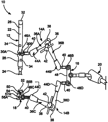
removing at least one of the first rigid retractor and the second rigid retractor from the patient and inserting an assembly blade that is mounted to a table and hands-free,
wherein the assembly blade is coupled to one of a plurality of articulating arms each with independent movability relative to the other articulating arm,
wherein the each articulating arm is configured to translate and angulate, each of the articulating arms including at least three articulating linkages pivotally coupled to each other,
wherein the first rigid retractor is spaced apart from the second rigid retractor,
wherein the assembly blade is attached to a handle portion at a proximal end of the assembly blade via a hinge mechanism disposed between the assembly blade and the handle portion, wherein the hinge mechanism is configured to allow the assembly blade and the handle portion to rotate about a point with respect to each other,
wherein the handle portion is elongated from a distal end to the proximal end and includes one or more tabs configured to hold a light source, and the distal end includes a curved portion configured to allow pulling of the assembly blade, and
wherein the hinge mechanism enables the assembly blade to move and lock in multiple different positions relative to the handle portion.
|