| CPC A47L 15/4291 (2013.01) [A47L 15/241 (2013.01); A47L 15/4287 (2013.01); A47L 15/46 (2013.01); A47L 15/486 (2013.01); A47L 15/488 (2013.01); A47L 2401/18 (2013.01); A47L 2501/10 (2013.01); A47L 2501/12 (2013.01)] | 17 Claims |
|
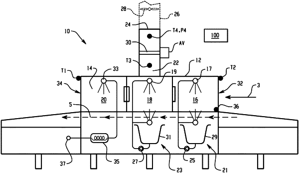
1. A warewash machine, comprising:
a housing defining a ware inlet, a ware outlet and an internal chamber running from the ware inlet to the ware outlet and through which wares are moved in a conveyance direction by a conveyor for cleaning, the internal chamber including a plurality of sequential spray zones including at least one wash zone and a rinse zone downstream of the wash zone in the conveyance direction;
a vent path from the chamber leading to a vent outlet for connecting to a building ventilation system;
a damper for controlling a flow area at a location along the vent path;
a controller connected to control a position of the damper, the controller configured to adjust a position of the damper based upon input from at least a first temperature sensor, wherein the first temperature sensor is located (i) proximate to the ware inlet, (ii) proximate to the ware outlet or (iii) along the vent path.
|