| CPC H01Q 1/2283 (2013.01) [H01Q 1/243 (2013.01); H01Q 1/36 (2013.01); H01Q 1/38 (2013.01); H01Q 5/357 (2015.01); H01Q 9/0407 (2013.01); H01Q 9/30 (2013.01); H01Q 19/005 (2013.01); H01Q 21/065 (2013.01); H01Q 21/20 (2013.01); H01Q 21/30 (2013.01)] |

| AS A RESULT OF REEXAMINATION, IT HAS BEEN DETERMINED THAT: |
| Claims 14 and 16 are cancelled. |
| Claims 1, 4, 9-10, 13 and 15 are determined to be patentable as amended. |
| Claims 2-3, 5-7, 11-12 and 17-20, dependent on an amended claim, are determined to be patentable. |
| Claim 8 was not reexamined. |
|
1. An antenna device comprising:
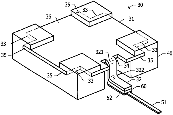
a radiation conductor constructed of a metal plate having a pair of main surfaces pointing in opposite directions, each main surface of the pair of main surfaces including a first surface region, the first surface region including at least a part of a peripheral edge portion of the main surface, at least one main surface of the pair of main surfaces including a second surface region, the second surface region being a region other than the first surface region;
a dielectric member holding the radiation conductor in such a manner that the first surface region of each main surface of the pair of main surfaces is sandwiched between portions of the dielectric member in a thickness direction of the radiation conductor
a lead-out portion leading out of the radiation conductor, the lead-out portion and the radiation conductor being constructed of one metal plate, a tip of the lead-out portion being exposed outside the dielectric member,]
wherein the second surface region of the at least one main surface is exposed to air [ ,
wherein the tip of the lead-out portion is fixed to a land with a conductive material, the land being on a mounting substrate and connected to a feed line, and
wherein the lead-out portion is bent in such a manner that the tip of the lead-out portion is closer to the mounting substrate than a point at which the lead-out portion leads out of the radiation conductor] .
|
|
4. The antenna device according to claim 1, further comprising
wherein the dielectric member has a facing surface facing the mounting substrate, at least a part of the facing surface being bonded to the mounting substrate with an adhesive.
|
|
9. The antenna device according to claim 1, further comprising:
a fixation portion leading out of the radiation conductor, the fixation portion and the radiation conductor being constructed of one metal plate, a tip of the fixation portion being exposed outside the dielectric member and being fixed to the mounting substrate.
|
|
10. The antenna device according to claim 1, further comprising:
a fixation portion fastened to the dielectric member and made of metal, wherein the dielectric member has a facing surface facing the mounting substrate, and the fixation portion is separated from the radiation conductor, is exposed at the facing surface of the dielectric member, and is fixed to the mounting substrate.
|
|
13. The antenna device according to claim 4, wherein the mounting substrate includes
|
|
15. The antenna device according to claim 13,
|